| 1 |
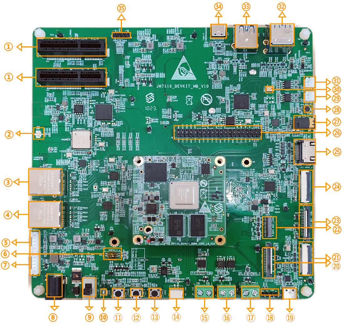
PCIE × 4 Connector |
JH-7110 DevKit
supports 2 PCIe × 4-lane connectors, but JH-7110 SoC only
support 1 lane. |
| 2 |
ANT Connector |
It is used for connect ANT. |
| 3 |
Ethernet Ports LAN1 |
The Ethernet port is for network data connection. |
| 4 |
Ethernet Ports LAN0 |
The Ethernet port is for network data connection. |
| 5 |
Charger I2C |
Power
supply for I2C. |
| 6 |
Boot Mode Pins |
It is provided to determine the boot mode before JH-7110 DevKit is
powered up. |
| 7 |
Battery |
- |
| 8 |
PWR In |
Power input. It is used to connect to the power supply. |
| 9 |
PWR Switch |
Power switch. It is used to power on/off the board. |
| 12 |
Power LED |
Power indicator light. |
| 11 |
Power On |
The button to turn on/off the power of the board, usually by pressing
the button. |
| 12 |
Reset |
- |
| 13 |
Wake |
- |
| 14 |
FAN |
It is used to connect to the fan. |
| 15 |
RS232 |
It is used for serial communication between devices. |
| 16 |
RS485 |
It is used for serial communication between devices. |
| 17 |
CAN |
It is used for data communication and data monitor. |
| 18 |
UART0 Debug |
- |
| 19 |
Type-C Debug |
- |
| 20 |
MIPI CSI 1C2L |
- |
| 21 |
MIPI CSI 1C4L |
- |
| 22 |
MIPI DSI 1C4L |
- |
| 23 |
MIPI DSI 1C2L |
- |
| 24 |
eDP |
The port for eDP screen. |
| 25 |
HDMI A |
HDMI A port. |
| 26 |
40Pin Out |
40-pin output. |
| 27 |
3.5mm Audio Jack |
3.5mm audio jack for audio output. |
| 28 |
MIC1 |
Microphone, which is used for audio input. |
| 29 |
SPK_R |
Right speaker. |
| 30 |
DMIC1 |
Digital Monolithic Integrated Circuit. |
| 31 |
SPK_L |
Left speaker. |
| 32 |
USB3.0 Type-A × 2 Connector |
2 × USB3.0 Type-A Connector |
| 33 |
USB3.0 Type-A Connector |
- |
| 34 |
Type-C Programming |
USB2.0 device for programming via Type-C port. |
| 35 |
I2C Header |
- |