To setup hardware, connect buttons pin ① and pin ② to the breadboard first, and then
connect pin ③ and pin ④ to VisionFive
2 or VisionFive 2
Lite. The
following table and figure describe how to connect button to the 40-pin GPIO
Header:
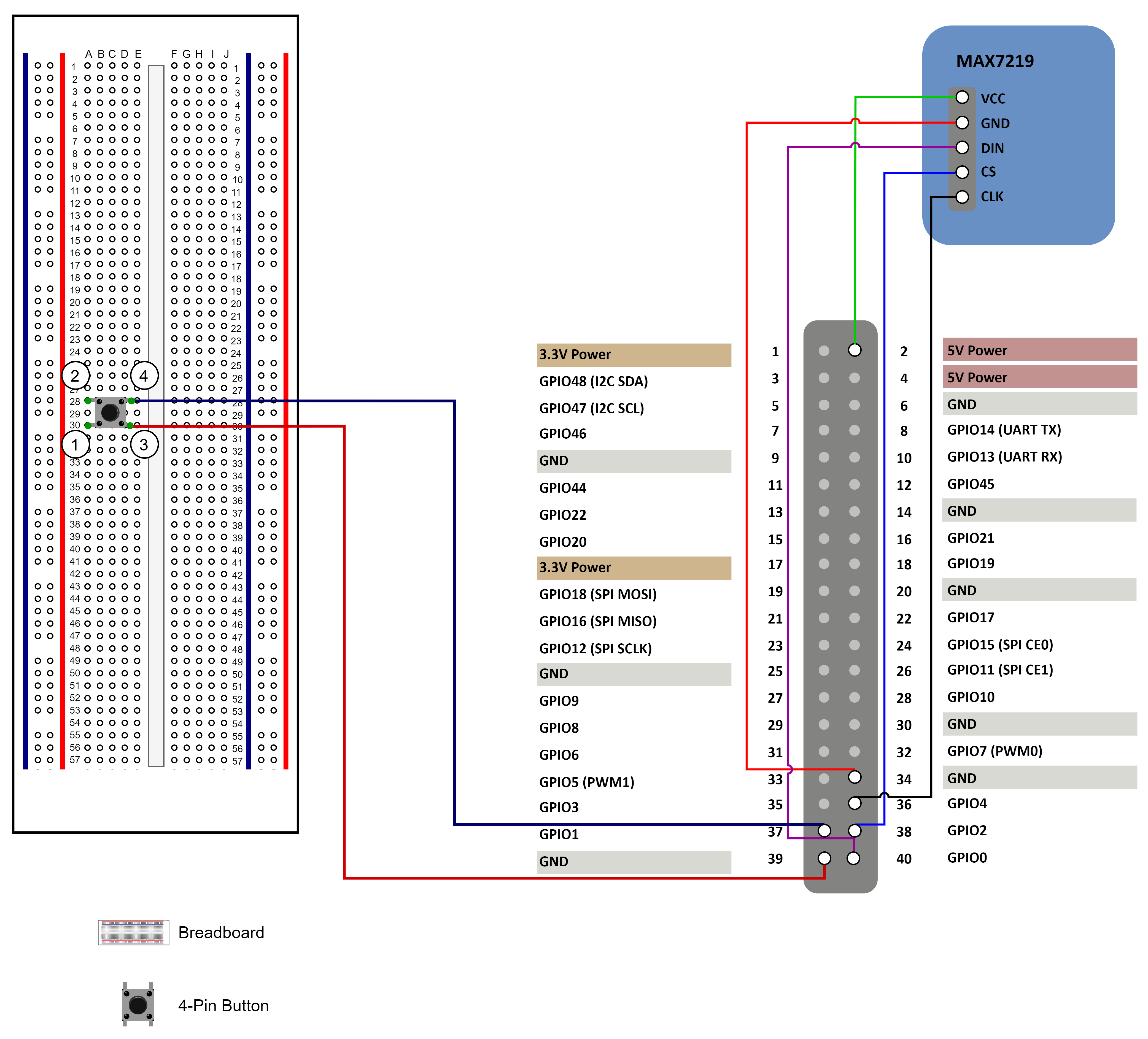
Table 1. Connect button to the 40-Pin Header
Button
40-Pin GPIO Header
Pin Number
Pin Name
Pin ④
37
GPIO60
Pin ③
39
GND
Table 2. Connect MAX7219 to the 40-Pin Header
MAX7219
40-Pin GPIO Header
Pin Number
Pin Name
VCC
2
5V Power
GND
34
GND
DIN
40
GPIO44
CS
38
GPIO61
CLK
36
GPIO36
Figure 1. Connect the button, MAX7219 to the 40-Pin Header
Tip: Inside the button, the pins ① and ③ are connected
while the pins ② and ④ are connected.