The above file contains all the Ethernet PHY supported (self-adaptive) by default in
U-Boot.
Exactly as described in this file, the system will initialize the PHY mentioned one by
one.
Note: If you find the boot-up process spends too much time,
by examining each PHY use, you may remove some unused PHY and leave only the
required ones.
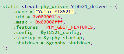
The following image shows a specific U-Boot PHY structure as an example. Figure 1. U-Boot PHY Structure Example
The following list provides descriptions for the above parameters.
.name: The name of the Ethernet PHY that you want to support,
and you can input a random name, but it is recommended to input a device-specific
name for future maintenance.
.uid: The manufacturer ID as well as the device ID of the
Ethernet PHY which can be found in the manual from the PHY manufacturer.
.mask: The mask of the Ethernet PHY, in the example,
“0x00000fff”, the position of digit of
“f” is the UID number. In practice, this digit can be
omitted to simplify the input.
.feature: The Gigabit feature of the PHY. For example,
whether the Ethernet PHY is a Gigabit PHY or not.
.config: The function call which introduces how to initialize
the Ethernet PHY. For most PHY, the configuration is not needed. For complex PHY
with QSGMI and RMII, the configuration is required to specify the role of the PHY.