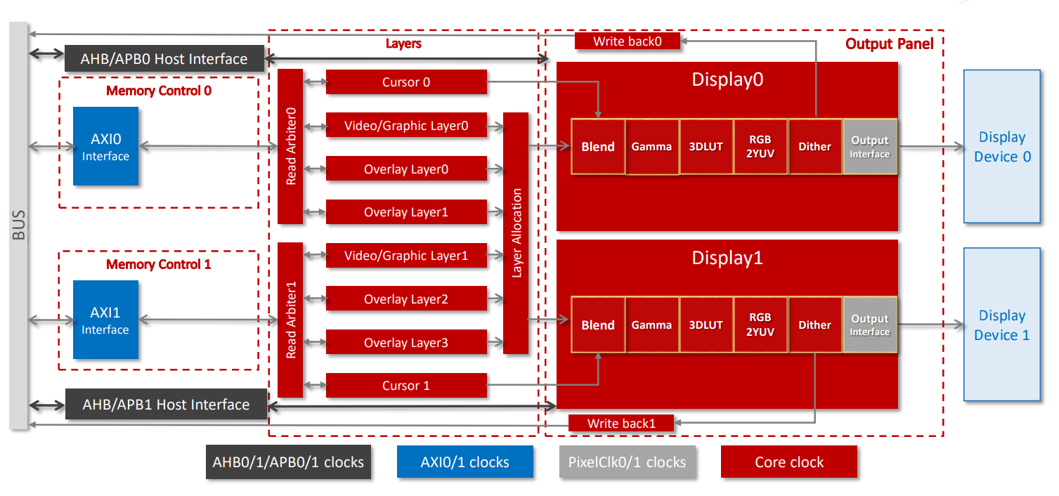
The following image shows the block diagram of the DC8200 display controller. Figure 1. DC8200 Display Controller Block Diagram
The following components are included.
Host Interface: Allows communication with the system and
the DC controller. The host interfaces include the AXI, AHB, and APB. In this
block, data crosses clock domain boundaries.
Memory Control: Contains the AXI interface to manage the
access between the system memory and layers of the DC8200.
Write Back: For debug use only.
Layers: Include video/graphic, overlay, and cursor
layers.
Video/graphic layers support both video and graphic configurations.
Video/graphic and overlay layers support dynamic layer allocation and
de-gamma.
Overlay 1 and overlay 3 do not support scaling, rotation, and line
buffers.
Cursor layers provide hardware cursor functionality.
Dither: Provides a Lookup Table (LUT).
Gamma: Performs gamma correction.
Output Panels: Support two output panels, as shown by
Display0 and Display1.
Output Interfaces: Support parallel pixel output with
30-bit Data, Horizontal Sync, Vertical Sync, and Data Enable. Support easy
adaptation to external serialization logic, for example, HDMI.
Pixel Pipelines: Reside in the layers and output panels.
Two display pipelines support linear and tiled frame buffers for RGB and YUV
inputs. Optional enhancements include multiple overlay layers, composition and
blending, up/down scaling with multi-tap filtering, and color space
conversions.
If you need more information, you may contact StarFive technical support and request
documentation from the third-party IP.