Hardware Setup
To setup hardware, connect buttons pin ① and pin ② to the breadboard first, and then
connect pin ③ and pin ④ to VisionFive
2 or VisionFive 2
Lite. The
following table and figure describe how to connect button to the 40-pin GPIO
Header:
| Button | 40-Pin GPIO Header | |
|---|---|---|
| Pin Number | Pin Name | |
| Pin ④ | 37 | GPIO60 |
| Pin ③ | 39 | GND |
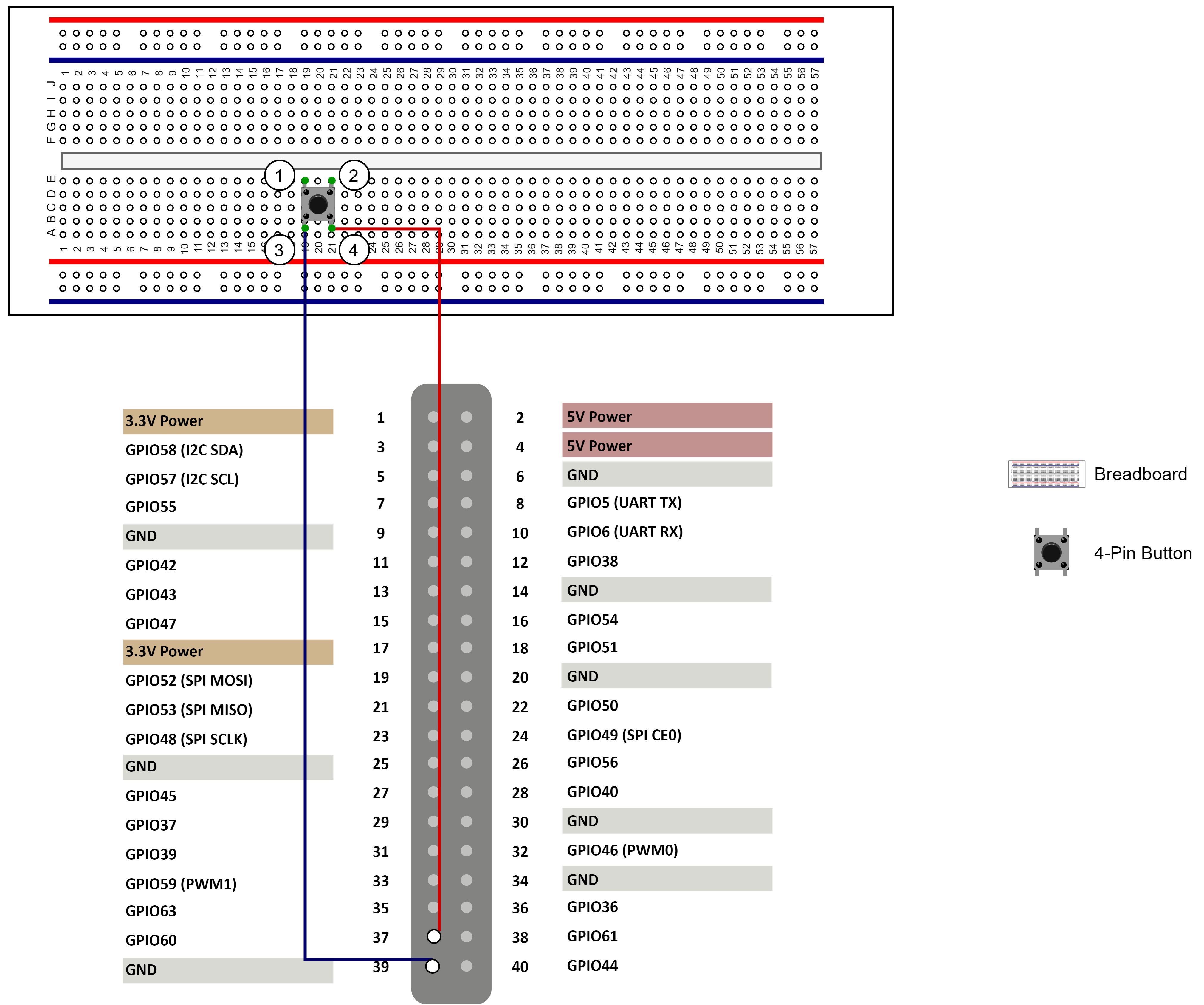
Tip: Inside the button, the pins ① and ③ are connected
while the pins ② and ④ are connected.