Modifying dts
To modify dts file, perform the following steps:
-
Add aliases of uart1 or uart2 on the aliases node. The following is an example:
Figure 1. Example Configuration 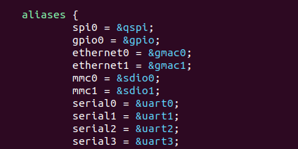
-
Add uart1 or uart2 node on the dts. The following is an example:
Figure 2. Example Configuration 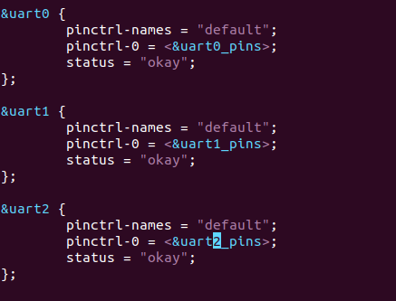
-
Add uart1_pins or uart2_pins node on the &gpio node:
Note:
The configured UART GPIO number is the number contained in the Pin Name. You can configure the unoccupied pins. For more details about the GPIO Pin Name, see the GPIO Pinout in this document.
Figure 3. Example Configuration 