Preparing Hardware
Prepare the following hardware items before running the demo code:
| Type | M/O* | Item | Notes |
|---|---|---|---|
| General | M | VisionFive 2 single board computer | - |
| General | M |
|
These items are used for flashing Debian OS into a micro-SD card. |
| GPIO Demo (LED) | M |
|
|
Breadboard Introduction
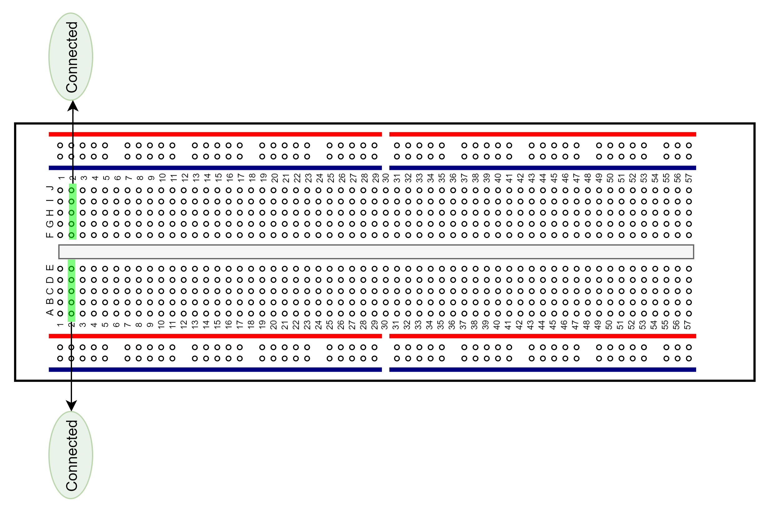
The breadboard is a way of connecting electronic components to each other without having to solder them together. They are often used to test a circuit design before creating a Printed Circuit Board (PCB). As shown in the following figure, there are two lines at the top and the bottom respectively of the breadboard. These two lines are used for power connection: the blue line is for negative and the red line is for positive. Besides, they are divided into two sections, and the holes in each section are connected.
In each column (from A to E, and F to J), holes are connected electrically. In each row (from 1 to 57), holes are not connected.