Specification
Feature Specification
| Type | Item | Description |
|---|---|---|
| Processor | StarFive JH-7110S | StarFive JH-7110S with RISC-V quad-core CPU with 2 MB L2 cache and a monitor core, supporting RV64GC ISA, working up to 1.25 GHz |
| Imagination GPU | IMGBXE-4-32 MC1 with work frequency up to 400MHz | |
| Memory | 2GB/4GB/8GB | LPDDR4SDRAM, up to 2,800 Mbps |
| Storage | Onboard TF card slot or eMMC | Either the eMMC or the TF card can be chosen. |
| QSPI Flash | The firmware to store U-Boot and BootLoader | |
| Multimedia | Video Output | 1× 2-lane MIPI DSI display port,
supporting up to 1080p@30fps 1× HDMI 2.0, supporting up to 4K@30fps or 2K@60fps |
| Camera | 1× 2-lane MIPI CSI camera port, supporting up to 1080p@30fps | |
| Encoder/Decoder | Video decoder supports up to 4K@60fps and multi-stream for
H264/H265 Video encoder supports up to 1080p@30fps and multi-stream for H265 JEPG encoder/decoder |
|
| Connectivity | Ethernet | 1× RJ45 Gigabit Ethernet ports |
| USB Host | 3× USB 2.0 and 1× USB 3.0/USB 2.0 ports (multiplexed with a PCIe 2.0 1× lane) | |
| USB Device | 1× USB device port (by reusing the USB-C port) | |
| M.2 Connector | M.2 M-Key, size: 2242 | |
| Wireless | Onboard WiFi 6 & BT 5.4 | |
| Power | USB-C port | USB Type C 5V / 3A |
| GPIO Power In | 5V DC via GPIO header | |
| PoE (Power over Ethernet) | Power function is enabled and requires separate PoE HAT | |
| GPIO | 40-Pin GPIO Header | 1× 40-pin GPIO header, supporting various interface
options:
|
| Button | Boot button | Used for recovering the BootLoader |
| Compliance | RoHS, FCC, CE | - |
| Environment | Recommended operating temperature | 0-50 ℃ |
| Other | Debug function | UART TX and UART RX are available through the 40-pin GPIO header |
| Fast boot mode | Used for flashing the OS image to the eMMC Short the J20 header by Jumper and power on, then the board will automatically enter the fastboot mode, the user can flash the OS image to the eMMC via USB-C |
Mechanical Specification
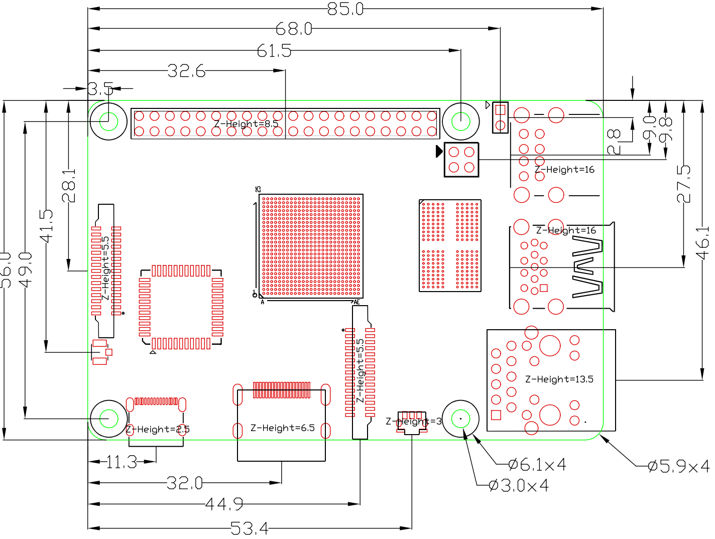
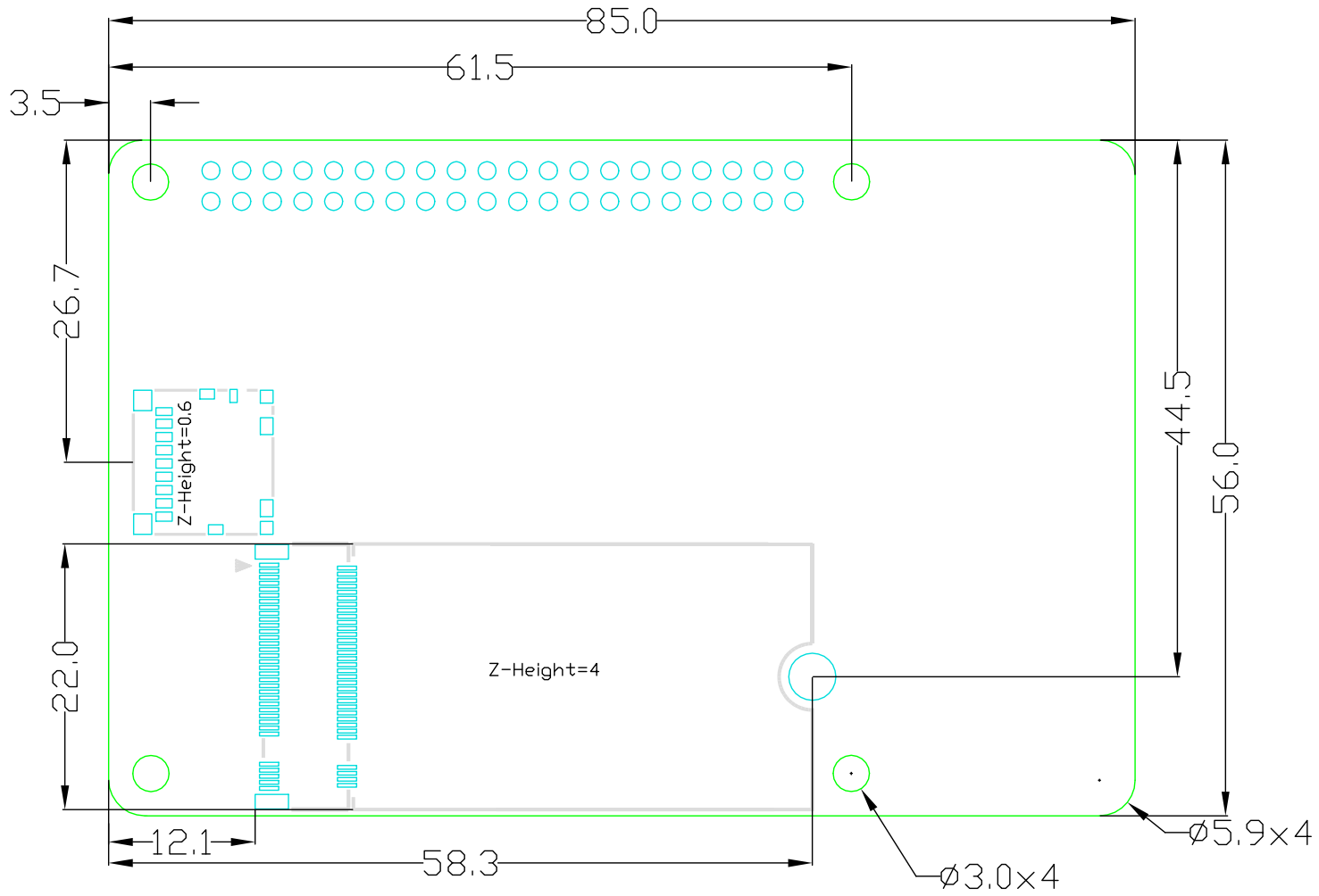
- Length: 85 mm
- Width: 56 mm
The following diagrams illustrate the mechanical drawings of VisionFive 2 Lite.
Use Spacers for NPTHs
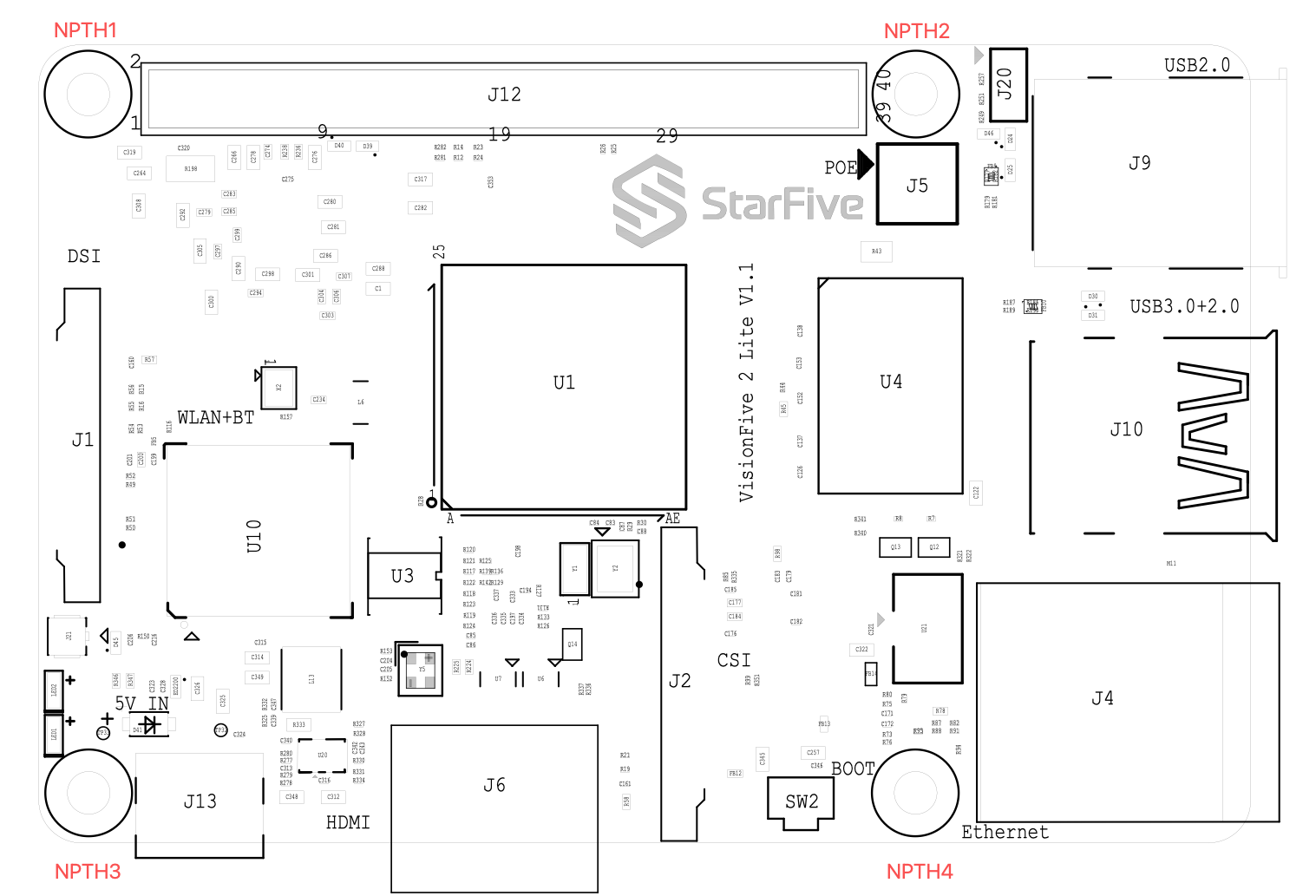
During the use of VisionFive 2 Lite, avoid contact with hard objects that may cause damage. StarFive recommends that you use spacers for the following NPTHs (Non Plating Through Hole):
- Single head hexagonal copper columns (Size: M2.5*10+6mm)
Figure 4. Single head hexagonal copper columns 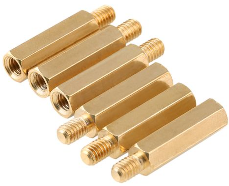
- Double way hexagon copper studs (Size: M2.5*4)
Figure 5. Double way hexagon copper studs 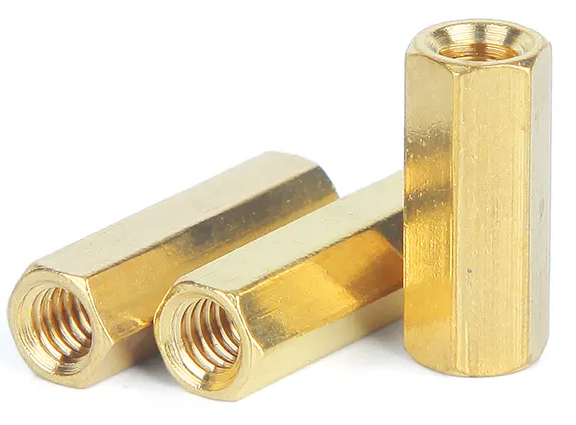
Electrical Specification
The following table lists the electrical specifications for VisionFive 2 Lite .
| Area | Specification |
|---|---|
| Input Power |
VisionFive 2 Lite supports various ways of powering, smart power adapter as well as fixed voltage:
|
| GPIO Voltage | The required voltage level for all GPIO pins is 3.3 V. |
Temperature Range and Thermals
The recommended ambient operating temperature range is from 0℃ to 50℃.
To reduce thermal output when idling or under light load, VisionFive 2 Lite reduces the CPU clock speed and voltage. During heavier load, the speed and voltage (and hence thermal output) are increased. The internal governor will throttle back both the CPU speed and voltage to make sure the CPU temperature never exceeds 85℃.
VisionFive 2 Lite will operate perfectly well without any extra cooling and is designed for sprint performance - expecting a light use case on average and ramping up the CPU speed when needed (for example, when loading a web page). If a user wishes to load the system continually or operate it at a high temperature at full performance, further cooling may be needed.
Board Appearance
The following figures illustrate the top and bottom views of the board.
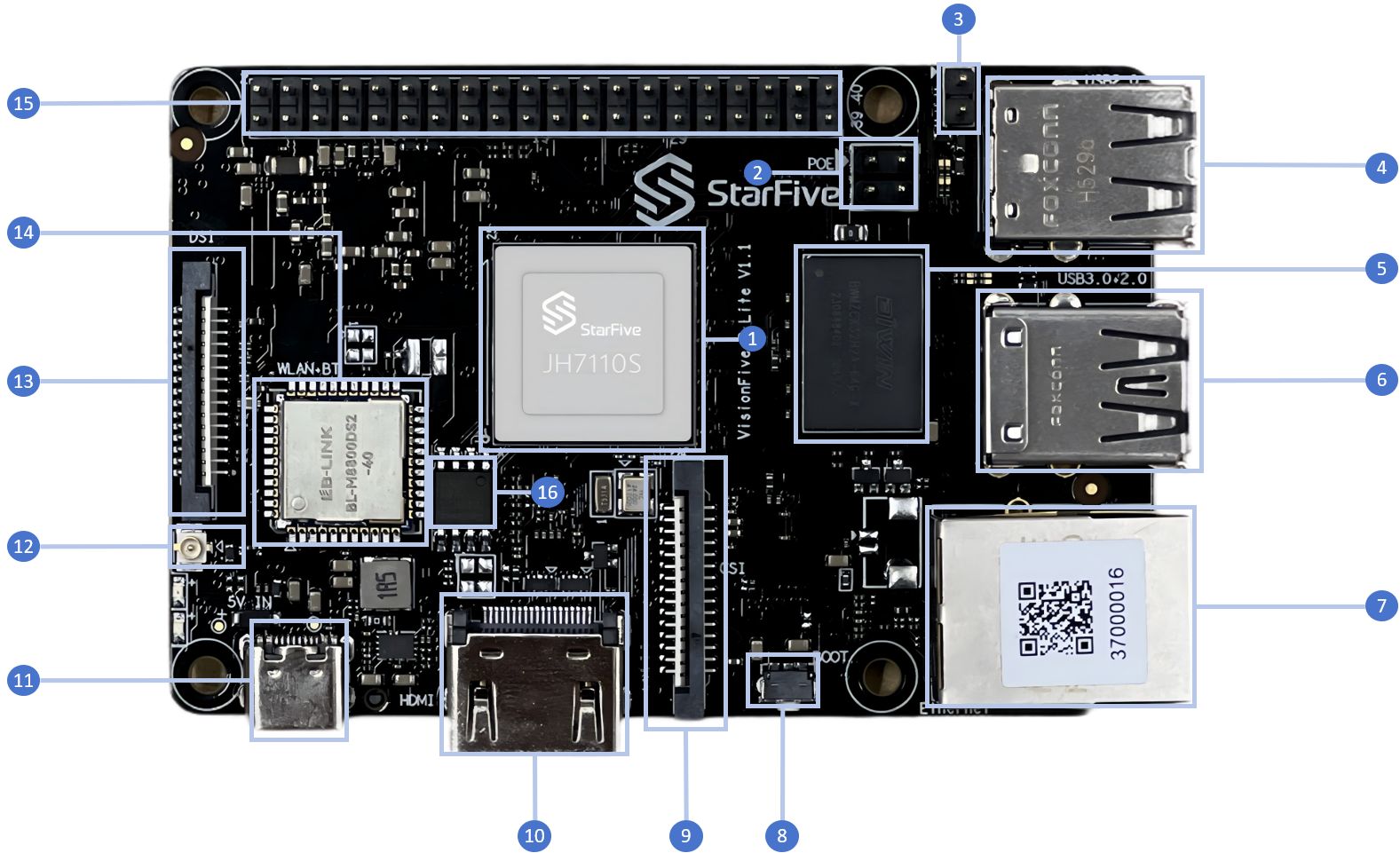
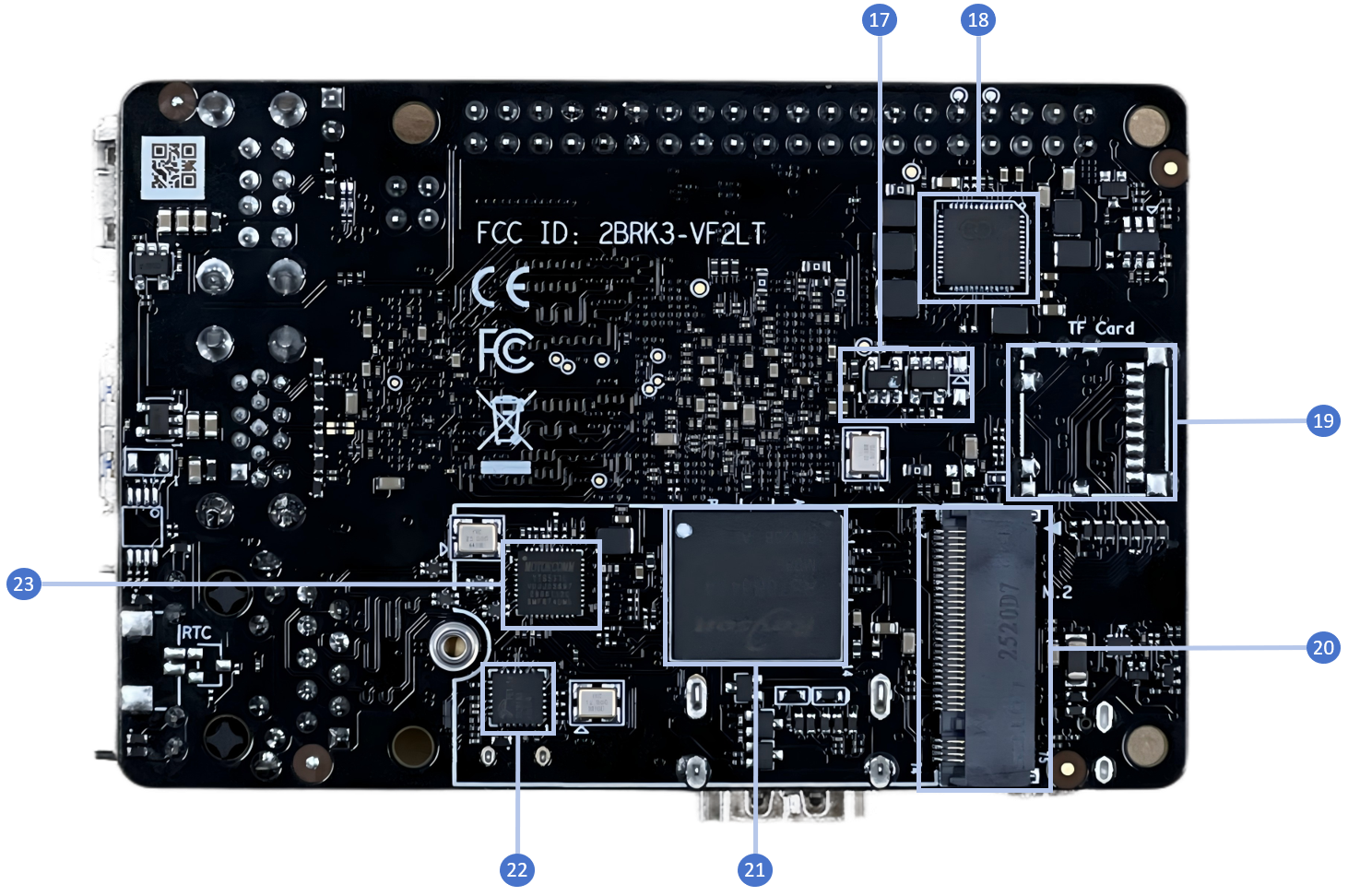
| No. | Description | No. | Description |
|---|---|---|---|
| 1 | StarFive JH-7110S with RISC-V quad-core CPU, supporting RV64GC ISA | 12 | 2.4G/5.8GHz Antenna Connector |
| 2 | PoE Header | 13 | 2-Lane MIPI DSI |
| 3 | Fastboot pins1 | 14 | WiFi/BT module |
| 4 | 2× USB 2.0 Port | 15 | 40-Pin GPIO Header |
| 5 | 2GB/4GB/8GB LPDDR4 SDRAM | 16 | QSPI Flash |
| 6 | 1× USB 3.0 Port and 1×USB 2.0 Port | 17 | EEPROM |
| 7 | 1× Ethernet Port (RJ45) | 18 | PMIC |
| 8 | Recovery Button | 19 | TF card slot (TF version) |
| 9 | 2-Lane MIPI CSI | 20 | M.2 M key |
| 10 | HDMI 2.0 Port | 21 | Onboard eMMC (eMMC version) |
| 11 | USB Type C | 22 | USB2.0 Hub FE1.1S |
| - | - | 23 | GMAC0 PHY |
GPIO Pinout
VisionFive 2 Lite uses the same GPIO header as VisionFive 2. See the following diagram for the VisionFive 2 Lite GPIO pinout.
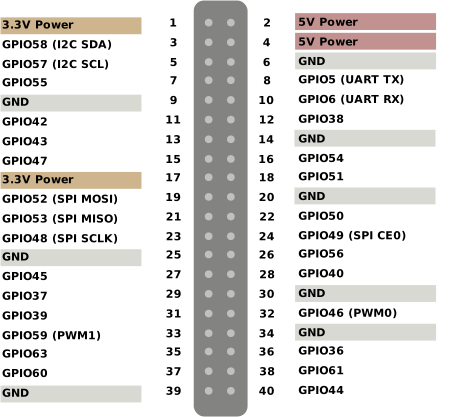
Each GPIO pin can safely draw a maximum current of 32 mA, whereas the maximum current draw when all GPIOs are combined should be less than 100 mA. Take this into account, otherwise, you end up destroying the GPIO pins.
All GPIOs can be configured to support different functions including but not limited to SDIO, Audio, SPI, I2C, UART, and PWM. As VisionFive 2 Lite uses the same GPIO header as VisionFive 2,see Configure and Debug with 40-Pin Header for VisionFive 2 Lite GPIO configuration.