Peripherals
GPIO
- 3.3 V (on 2 pins)
- 5 V (on 2 pins)
- Ground (on 8 pins)
- GPIO
- CAN bus
- DMIC
- I2C
- I2S
- PWM
- SPI
- UART
The following table describes the GPIO pin assignments:
| Pin Name | Pin No. | Pin No. | Pin Name |
|---|---|---|---|
| +3.3V | 1 | 2 | +5V |
| GPIO58 (I2C SDA) | 3 | 4 | +5V |
| GPIO57 (I2C SCL) | 5 | 6 | GND |
| GPIO55 | 7 | 8 | GPIO5 (UART TX) |
| GND | 9 | 10 | GPIO6 (UART RX) |
| GPIO42 | 11 | 12 | GPIO38 |
| GPIO43 | 13 | 14 | GND |
| GPIO47 | 15 | 16 | GPIO54 |
| +3.3V | 17 | 18 | GPIO51 |
| GPIO52 (SPI MOSI) | 19 | 20 | GND |
| GPIO53 (SPI MISO) | 21 | 22 | GPIO50 |
| GPIO48 (SPI SCLK) | 23 | 24 | GPIO49 (SPI CE0) |
| GND | 25 | 26 | GPIO56 |
| GPIO45 | 27 | 28 | GPIO40 |
| GPIO37 | 29 | 30 | GND |
| GPIO39 | 31 | 32 | GPIO46 (PWM0) |
| GPIO59 (PWM1) | 33 | 34 | GND |
| GPIO63 | 35 | 36 | GPIO36 |
| GPIO60 | 37 | 38 | GPIO61 |
| GND | 39 | 40 | GPIO44 |
All GPIOs can be switched (multiplexed) to support different functions including but not limited to SDIO, Audio, DMIC, SPI, I2C, UART, PWM, and CAN bus. For detailed instructions, see Configure and Debug with 40-Pin Header.
Camera
VisionFive 2 Lite has 1× 2-lane MIPI CSI camera port, supporting up to 1080p@30fps.
The following figure and table describe the 2-lane MIPI DSI definition:
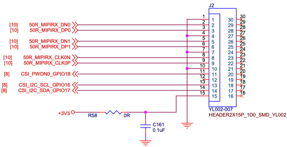
| No. | Definition | Description | Voltage |
|---|---|---|---|
| 1 | GND | Ground | - |
| 2 | 50R_MIPIRX_DN0 | MIPI Input Lane 0 Negative | 1.8V |
| 3 | 50R_MIPIRX_DP0 | MIPI Input Lane 0 Positive | 1.8V |
| 4 | GND | Ground | - |
| 5 | 50R_MIPIRX_ DN1 | MIPI Input Lane 1 Negative | 1.8V |
| 6 | 50R_MIPIRX_ DP1 | MIPI Input Lane 1 Positive | 1.8V |
| 7 | GND | Ground | - |
| 8 | 50R_MIPIRX_CLK0N | MIPI Input Clock 0 Negative | 1.8V |
| 9 | 50R_MIPIRX_CLK0P | MIPI Input Clock 0 Positive | 1.8V |
| 10 | GND | Ground | - |
| 11 | CSI_PWDN0_GPIO18 | CSI power control | 3.3V |
| 12 | NC | NC | - |
| 13 | CSI_I2C_SCL_GPIO16 | CSII2C SCL | 3.3V |
| 14 | CSI_I2C_SDA_GPIO17 | CSII2C SDA | 3.3V |
| 15 | +3.3 V | Power Voltage for digital circuit 3.3 V | 3.3V |
Display
- 1× 2-lane MIPI DSI display port, supporting up to 1080p@30fps
- 1× HDMI 2.0, supporting up to 4K@30fps or 2K@60fps
The following figure and table describe the 2-lane MIPI DSI definition:
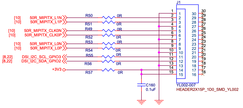
| PIN NO. | Pin Definition | Description | Voltage |
|---|---|---|---|
| 1 | GND | Ground | - |
| 2 | 50R_MIPITX_L1N | MIPI Output Lane 1 Negative | 1.8V |
| 3 | 50R_MIPITX_L1P | MIPI Output Lane 1 Positive | 1.8V |
| 4 | GND | Ground | - |
| 5 | 50R_MIPITX_CLK0N | MIPI Output Clock 0 Negative | 1.8V |
| 6 | 50R_MIPITX_CLK0P | MIPI Output Clock 0 Positive | 1.8V |
| 7 | GND | Ground | - |
| 8 | 50R_MIPITX_L0N | MIPI Output Lane 0 Negative | 1.8V |
| 9 | 50R_MIPITX_L0P | MIPI Output Lane 0 Positive | 1.8V |
| 10 | GND | Ground | - |
| 11 | DSI_I2C_SCL_GPIO3 | DSII2C SCL | 3.3V |
| 12 | DSI_I2C_SDA_GPIO2 | DSII2C SDA | 3.3V |
| 13 | GND | Ground | - |
| 14 | +3.3V | Power Voltage for digital circuit 3.3 V | 3.3V |
| 15 | +3.3V | Power Voltage for digital circuit 3.3 V | 3.3V |
USB Host
3× USB 2.0 and 1× USB 3.0/USB 2.0 ports (multiplexed with a PCIe 2.0 1× lane).
USB Device Port
1× USB device port by reusing the USB-C port.
HDMI
1× HDMI 2.0, supporting up to 4K@30fps or 2K@60fps.
M.2 Connector
M.2 M-Key SSD socket with 1× PCIe 2.0 interface, providing high speed storage access.
Gigabit Ethernet Port
1× RJ45 Gigabit Ethernet port.
PoE Header
VisionFive 2 Lite provides Power over Ethernet (PoE) function. PoE carries electrical power through data cables, and reduces the cabling requirements for network devices. You can use this function by adding a separate PoE HAT out of our product package.
Fastboot Header
1× 2-pin fastboot header. Users can enter the fastboot mode by using this header. For details, see Enter Fastboot Mode.
Boot Button
1× Boot button for recovering the bootloader.
For detailed instructions, see the Run Ubuntu on VisionFive 2 Lite.