Introduction
This application note provides the steps for the application of OpenPLC based on VisionFive 2 and VisionFive 2 Lite. The OpenPLC application used is adapted to the platform of VisionFive 2 and VisionFive 2 Lite
Official repository: https://github.com/thiagoralves/OpenPLC_v3
The overview of OpenPLC can be seen below:
| Overview of OpenPLC | ||
|---|---|---|
| Functions | Items | Usage |
| Input/Output | Digital input(8) | Gets digital input |
| Digital output(8) | Produces digital output | |
| Analog output(1) | Produces analog(pwm) output | |
|
Communication protocol |
Modbus RTU(Serial) | Modbus-RTU master device |
| Modbus TCP | Modbus-TCP master/slave device; Connect Scada | |
| DNP3 | Connect Scada | |
| Ethernet/IP | Connect Scada | |
| HMI(internal) | Dashboard | View the status of OpenPLC |
| Program | Upload PLC program | |
| Slave device | Connect&config slave devices | |
| Monitoring | Viewpoints value | |
| Scada | FUXA |
Support OPCUA, Modbus-TCP, Modbus-RTU, BACnet. Siemens-S7, Ethernet/IP |
| ScadaBR | Support DNP3, Modbus-TCP, Modbus-RTU, BACnet... | |
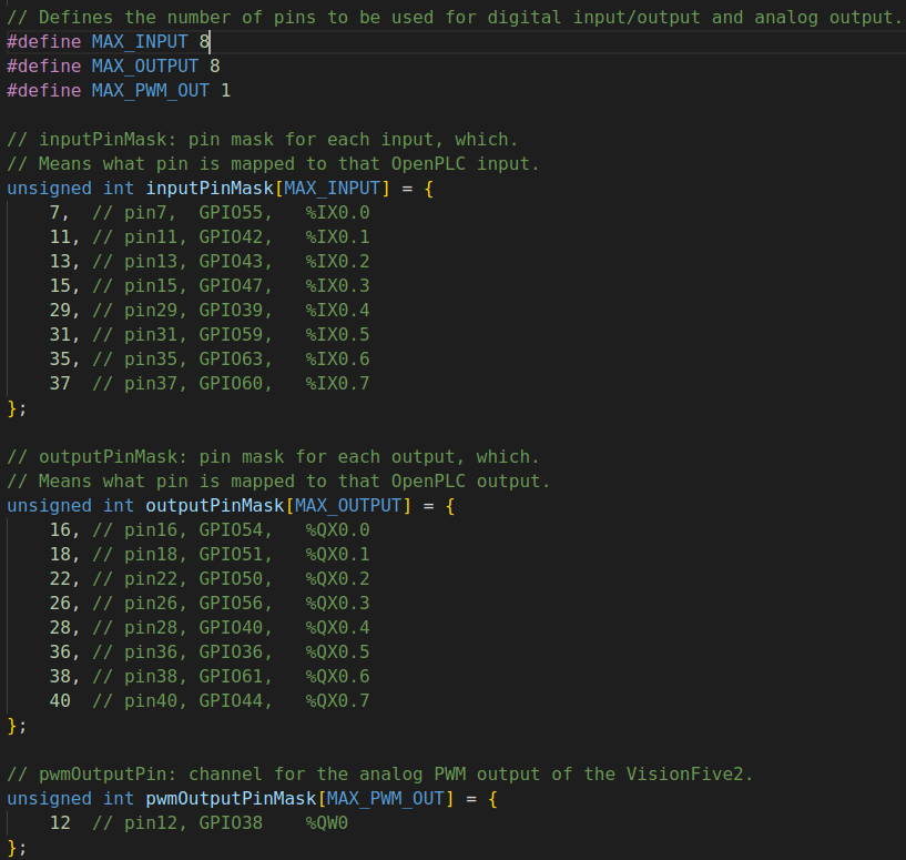
There are 8 digital inputs, 8 digital outputs, and 1 analog output defined in VisionFive 2 and VisionFive 2 Lite hardware layer, pins distribution are shown below:
| OpenPLC I/O | Pin name | Pin num | Pin num | Pin name | OpenPLC I/O |
|---|---|---|---|---|---|
| 3v3 Power | 3v3 Power | 1 | 2 | 5V Power | 5v Power |
| N/A | GPIO 58 (I2C SDA) | 3 | 4 | 5V Power | 5v Power |
| N/A | GPIO 57 (I2C SCL) | 5 | 6 | Ground | Ground |
| %IX0.0 | GPIO 55 (GPCLK0) | 7 | 8 | GPIO 5 (UART TX) | N/A |
| Ground | Ground | 9 | 10 | GPIO 6 (UART RX) | N/A |
| %IX0.1 | GPIO 42 | 11 | 12 | GPIO 38 (PCM CLK) | %QW0 |
| %IX0.2 | GPIO 43 | 13 | 14 | Ground | Ground |
| %IX0.3 | GPIO 47 | 15 | 16 | GPIO 54 | %QX0.0 |
| 3v3 Power | 3v3 Power | 17 | 18 | GPIO 51 | %QX0.1 |
| N/A | GPIO 52 (SPI MOSI) | 19 | 20 | Ground | Ground |
| N/A | GPIO 53 (SPI MISO) | 21 | 22 | GPIO 50 | %QX0.2 |
| N/A | GPIO 48 (SPI SCLK) | 23 | 24 | GPIO 49 (SPI0 CE0) | N/A |
| Ground | Ground | 25 | 26 | GPIO 56 | %QX0.3 |
| N/A | GPIO 45 | 27 | 28 | GPIO 40 | %QX0.4 |
| %IX0.4 | GPIO 37 | 29 | 30 | Ground | Ground |
| %IX0.5 | GPIO 39 | 31 | 32 | GPIO 46 (PWM0) | N/A |
| N/A | GPIO 59 (PWM1) | 33 | 34 | Ground | Ground |
| %IX0.6 | GPIO 63 | 35 | 36 | GPIO 36 | %QX0.5 |
| %IX0.7 | GPIO 60 | 37 | 38 | GPIO 61 | %QX0.6 |
| Ground | Ground | 39 | 40 | GPIO 44 | %QX0.7 |
OpenPLC Runtime uses the IEC 61131-3 nomenclature to address input (I), output (Q), and memory (M) locations. Moreover, memory bits (%MX) locations were not implemented, create any variable of type bool with no location (leave location blank) for it to serve as memory bits. If those variables need to be accessed by Modbus, locate those variables in the %QX area outside of device bounds, for example ‘%QX80.0’. More details can be seen at: https://openplcproject.com/docs/2-3-input-output-and-memory-addressing/
In the table above, %IX0.x, %QX0.x and %QWx represent digital input, digital output, and analog output respectively. All these I/Os are controlled by python lib:’Visionfive.gpio’. The pin num that is marked green indicates that this pin can be enabled by the Python library. More details of ‘VisionFive.gpio’ can be seen in Preparing Software.
The physical pins and number (if VisionFive.gpio supports) of OpenPLC I/O can be defined in the hardware layer file (openplc_v3/webserver/core/hardware_layers/VisionFive2_py.cpp):