Temperature Control
A demo of temperature control through OpenPLC and the information of each component can be viewed comprehensively through FUXA is given in this section.
| Items | Number | Note |
|---|---|---|
| VisionFive 2 or VisionFive 2 Lite | 1 | Modbus-RTU master device. |
| Arduino UNO | 1 | Modbus-RTU slave device. |
| LM35 | 1 | Temperature sensor. |
| L298N | 1 | Motor drive board. |
| Voltage converter | 1 | A 5V input voltage is provided to the motor. |
| DC motor | 1 | Turn the fan. |
| Breadboard | 1 | |
| LED | 2 | Preferably two different colors. |
| Button | 2 | |
| Dupont line | Several | |
| USB2Serial | 1 | Corresponding to the enabled type in the kernel options. |
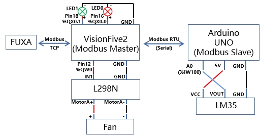
The overall system structure diagram is shown in the figure below. Since VisionFive2 lacks analog input, Arduino UNO is used as a slave device controlled by VisionFive 2 or VisionFive 2 Lite through Modbus RTU (serial) to read the input of temperature sensor LM35 and send it back to VisionFive2. Based on the obtained temperature information, VisionFive 2 or VisionFive 2 Lite reflects the temperature is in the normal/high range through the LED, outputs PWM signals with different duty ratios according to different temperature ranges, and controls fan start-stop and speed through the DC motor drive module L298N. All information on the system is transferred to FUXA via Modbus TCP.

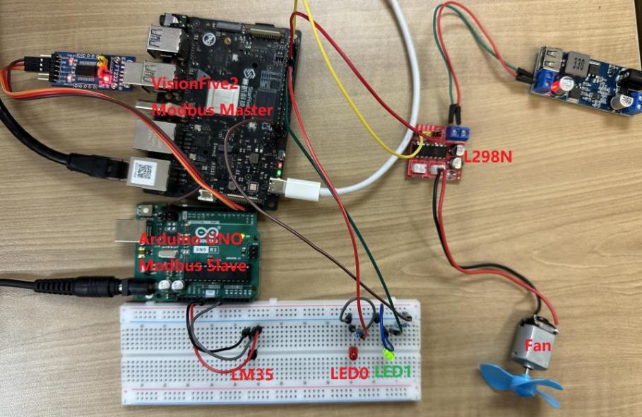
The physical connection is as follows:

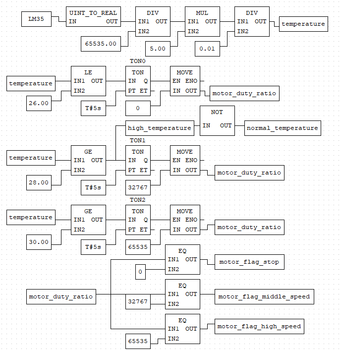
PLC functional block program and variable definition as shown below:


In OpenPLC, the analog input resolution is 16 bits, that is, the analog input in OpenPLC ranges from 0 to 65535. In the function diagram program, the value of the analog input LM35 (%IW100) needs to be converted into the temperature value. For every 1 degree Celsius rise in temperature, the output voltage of LM35 rises by 10mV. Therefore, ‘temperature = LM35 / 65535.00 * 5.00 / 0.01’.
In this function diagram program, if the temperature remains below 28 degrees Celsius, the fan will not work. When the temperature exceeds 28 degrees Celsius for 5s or more, VisionFive2's analog output pin(%QW0) outputs a 50% duty ratio PWM signal to drive the fan. When the temperature continues to rise above 30 degrees, the drive fan works at full load. The fan will not stop working until the temperature is below 26 degrees Celsius and lasts for more than 5 seconds.
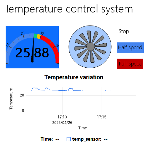
After completing program writing and uploading, slave-device connection, and FUXA setting, OpenPLC can be started to check the status of the whole temperature control system in FUXA

