Conveyor Screening Control
| Devices | Num | Note | |
|---|---|---|---|
| 1 | VisionFive 2 | 2 |
One acts as master and the other as a slave. Connect to relay HAT and step motor driver HAT respectively. |
| 2 | Arduino UNO | 1 | As a signal-receiving device of the weighing sensor, and transmit it to VisionFive 2. |
| 3 | Relay HAT | 1 | Used to control the conveyor belt. |
| 4 | Step motor driver HAT | 1 | Used to control the step motor. |
| 5 | Step Motor | 1 | Perform filtering actions. |
| 6 | Load cell with HX711 | 1 | Weighting products and converting analog signals into digital signals. |
| 7 | Conveyor & controller | 1 | Conveying products. |
| 8 | Infrared sensor | 1 | Determine whether there is a product through. |
| 9 | Dupont Line | - | |
| 10 | Cube | - | Plastic and wood cubes, as the product on the conveyor. |
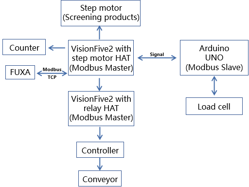
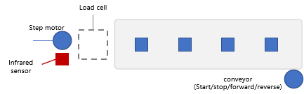
This demo is planed to show the scenarios of conveyor control and product screening.
It is composed of VisionFive 2, Arduino UNO, a conveyor, a weighing sensor, an infrared counter, and a stepper motor:
- VisionFive 2 with step motor HAT: As Modbus master, controls step motor, and infrared sensor directly and transfers the information to FUXA;
- VisionFive 2 with relay HAT: As Modbus slave, controls conveyor;
- Arduino UNO: As load cell controller, get the value of the weighting sensor;
- Step motor: Combined with the lead screw, used to push the product to the sides;
- Load cell: Determine whether the weight is up to standard;
- Infrared sensor: Sensing objects within a certain distance;
Both the relay board and the stepper motor driver board each occupy different GPIO pins. The assignments of these GPIO pins can be found on the following website:
https://www.waveshare.net/wiki/Stepper_Motor_HAT
https://www.waveshare.net/wiki/RPi_Relay_Board_(B)#.E5.BC.80.E5.8F.91.E8.B5.84.E6.96.99
| Relay board | Step motor driver board | ||
|---|---|---|---|
| Pin num | Function | Pin num | Function |
| 29 | Relay1 | 33 | A1A2B1B2 dir |
| 31 | Relay2 | 35 | A1A2B1B2 step |
| 33 | Relay3 | 32 | A1A2B1B2 enable |
| 36 | Relay4 | 36,11,38 | A1A2B1B2 mode |
| 35 | Relay5 | 18 | A3A4B3B4 dir |
| 38 | Relay6 | 12 | A3A4B3B4 step |
| 40 | Relay7 | 7 | A3A4B3B4 enable |
| 37 | Relay8 | 40,15,13 | A3A4B3B4 mode |
The relay board utilizes the Relay4/Relay6/Relay7/Relay8 channels, while the stepper motor driver board uses the A3A4B3B4 channels. Therefore, the pin assignments for these two boards are as follows:
| SM | default | Pin | Pin | default | SM |
|---|---|---|---|---|---|
| enable | %IX0.0 | 7 | 12 | %QW0 | step |
| %IX0.0 | %IX0.1 | 11 | 16 | %QX0.0 | %QX0.0 |
| mode | %IX0.2 | 13 | 18 | %QX0.1 | dir |
| mode | %IX0.3 | 15 | 22 | %QX0.2 | %QX0.1 |
|
%IX0.1 /IS |
N/A | 27 | 26 | %QX0.3 | %QX0.2 |
| %IX0.2 | %IX0.4 | 29 | 28 | %QX0.4 | %QX0.3 |
| %IX0.3 | %IX0.5 | 31 | 36 | %QX0.5 | %QX0.4 |
| %IX0.4 | %IX0.6 | 35 | 38 | %QX0.6 | motor_trig |
| motor_trig | %IX0.7 | 37 | 40 | %QX0.7 | mode |
| RB | default | Pin | Pin | default | RB |
|---|---|---|---|---|---|
| %IX0.0 | %IX0.0 | 7 | 12 | %QW0 | %QW0 |
| %IX0.1 | %IX0.1 | 11 | 16 | %QX0.0 | %QX0.0 |
| %IX0.2 | %IX0.2 | 13 | 18 | %QX0.1 | %QX0.1 |
| %IX0.3 | %IX0.3 | 15 | 22 | %QX0.2 | %QX0.2 |
|
%IX0.4 /IS |
N/A | 27 | 26 | %QX0.3 | %QX0.3 |
| %IX0.5 | %IX0.4 | 29 | 28 | %QX0.4 | %QX0.4 |
| %IX0.6 | %IX0.5 | 31 | 36 | %QX0.5 |
%QX0.5 Relay4 |
| %IX0.7 | %IX0.6 | 35 | 38 | %QX0.6 |
%QX0.6 Relay6 |
|
%QX1.0 Relay8 |
%IX0.7 | 37 | 40 | %QX0.7 |
%QX0.7 Relay7 |
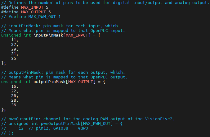
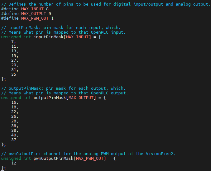
And the hardware layer of these two boards can be modified as:
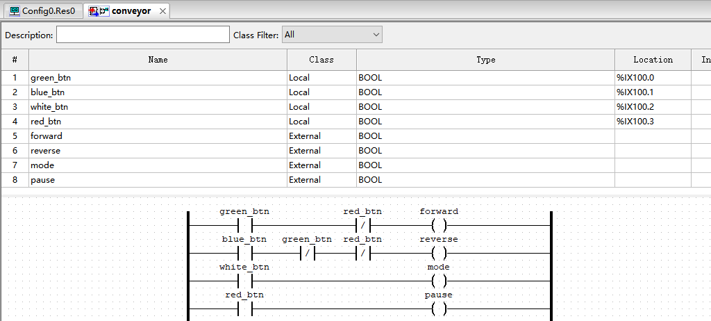
The PLC program for this demo consists of five parts: motor, clock2unclock_control, unclock2clock_control, sensor, and conveyor:

The ‘conveyor’ is for controlling the logic of forward/reverse/mode_selection/pause in the conveyor controller, which is manifested externally through the on/off state of the green/blue/white/red buttons on the controller.
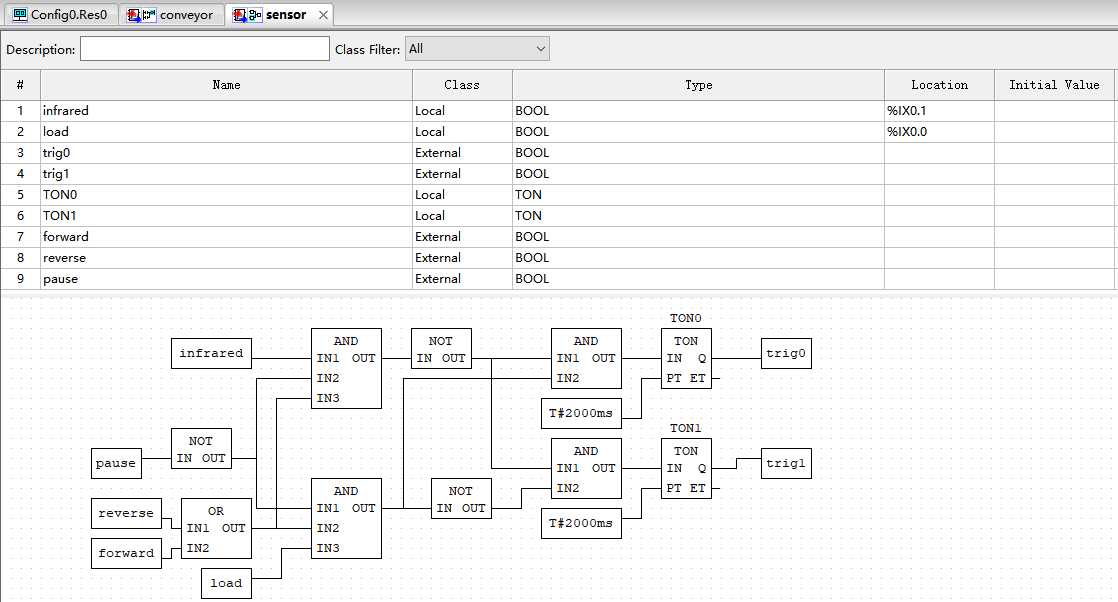
The ‘sensor’ is for receiving information from the infrared and weighing sensors. It uses the infrared sensor to determine if there is an object on the weighing sensor. It also uses the signal from the weighing sensor to determine if the weight of the item meets the standards. Based on these inputs, B outputs different control signals:
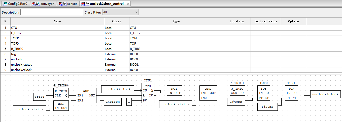
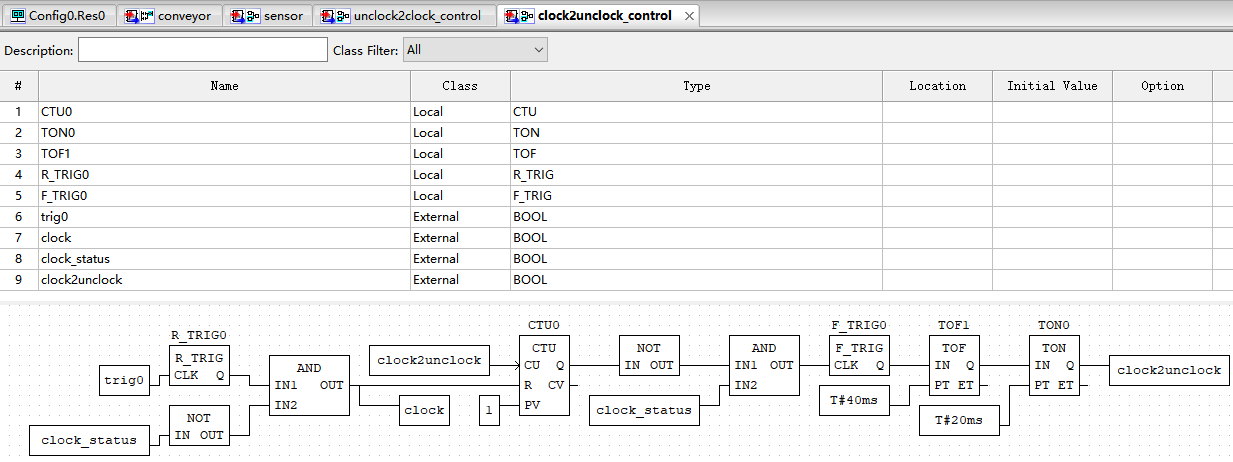
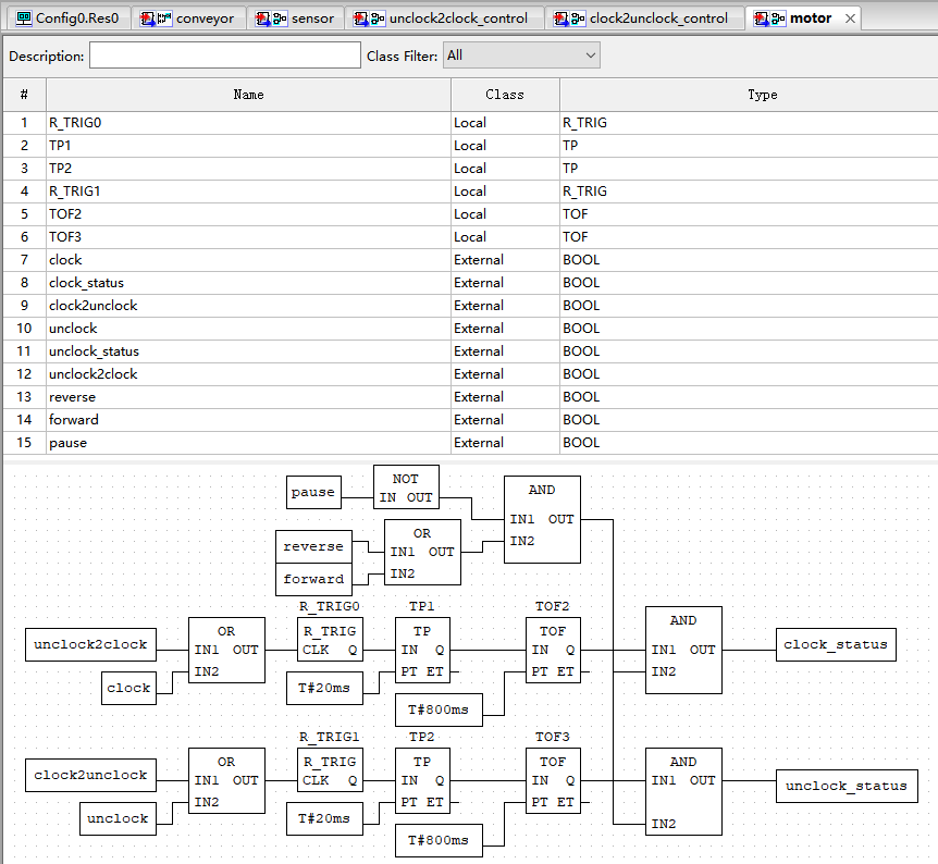
The ‘unclock2clock_control’ and ‘clock2unclock_control’ are for receiving signals from C and performing different forward and reverse logic respectively:
The ‘motor’ is responsible for receiving signals from ‘unclock2clock_control’ and ‘clock2unclock_control’ to control the output of forward and reverse signals:
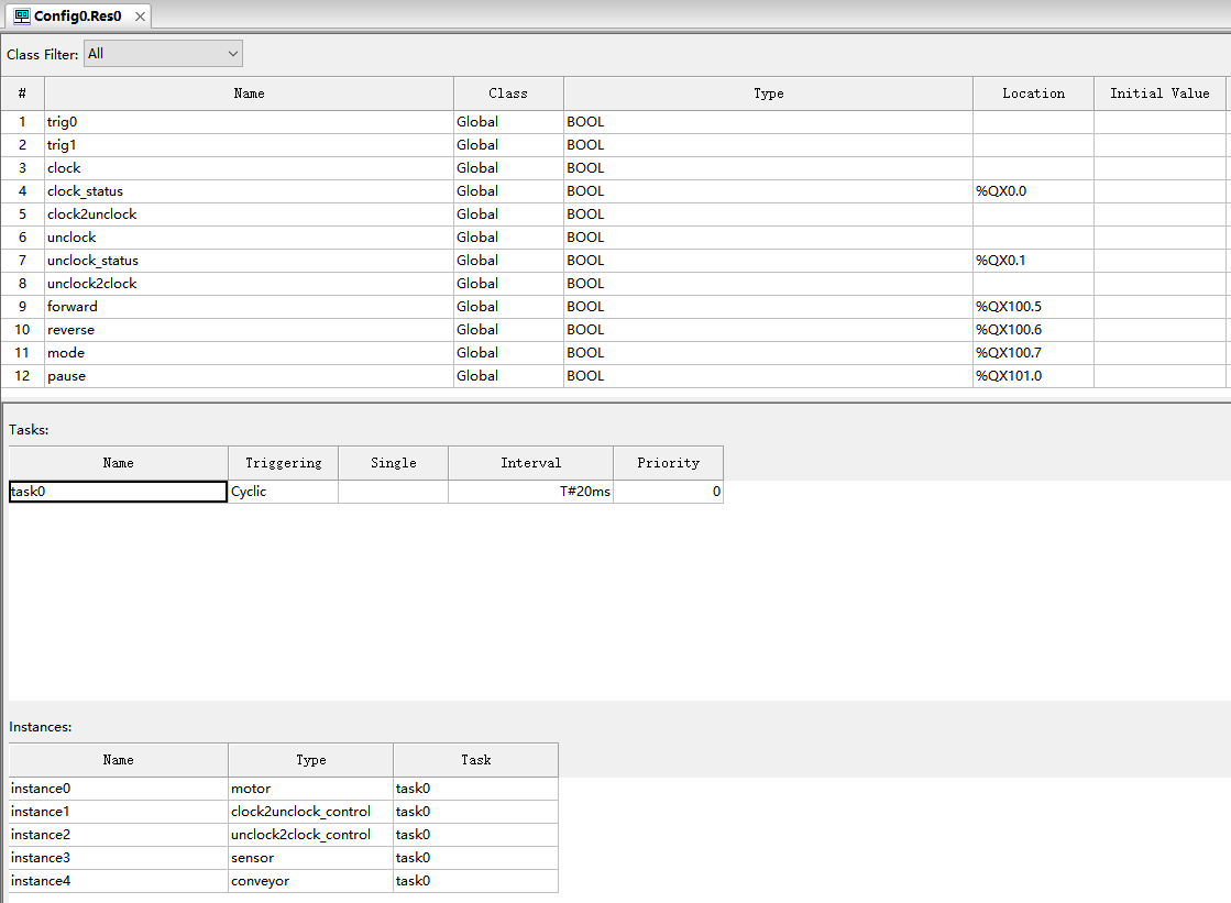
The global variable and instances settings are given as:
Functional block diagram program is located in
\\192.168.110.4\Starfivetech-Share\[group-share_in_group]\Software\SW_projects\VisionFive\Gen2\Applications\02_PLC\Program
Step motor driver program DRV8825.py and motor_trig.py are given as:
DRV8825.py:
import VisionFive.gpio as GPIO
import time

MotorDir = [
    'forward',
    'backward',
]

ControlMode = [
    'hardward',
    'softward',
]

class DRV8825():
    def __init__(self, dir_pin, step_pin, enable_pin, mode_pins):
        self.dir_pin = dir_pin
        self.step_pin = step_pin
        self.enable_pin = enable_pin
        self.mode_pins = mode_pins

        # GPIO.setmode(GPIO.BCM)
        # GPIO.setwarnings(False)
        GPIO.setup(self.dir_pin, GPIO.OUT, pull_up_down=GPIO.PUD_OFF, initial=GPIO.LOW)
        GPIO.setup(self.step_pin, GPIO.OUT, pull_up_down=GPIO.PUD_OFF, initial=GPIO.LOW)
        GPIO.setup(self.enable_pin, GPIO.OUT, pull_up_down=GPIO.PUD_OFF, initial=GPIO.LOW)
        for mode_pin in self.mode_pins:
            GPIO.setup(mode_pin, GPIO.OUT, pull_up_down=GPIO.PUD_OFF, initial=GPIO.LOW)

    def digital_write(self, pin, value):
        GPIO.output(pin, value)

    def Stop(self):
        self.digital_write(self.enable_pin, 0)

    def SetMicroStep(self, mode, stepformat):
        """
        (1) mode
            'hardward' :    Use the switch on the module to control the microstep
            'software' :    Use software to control microstep pin levels
                Need to put the All switch to 0
        (2) stepformat
            ('fullstep', 'halfstep', '1/4step', '1/8step', '1/16step', '1/32step')
        """
        microstep = {'fullstep': (0, 0, 0),
                     'halfstep': (1, 0, 0),
                     '1/4step': (0, 1, 0),
                     '1/8step': (1, 1, 0),
                     '1/16step': (0, 0, 1),
                     '1/32step': (1, 0, 1)}

        print("Control mode:",mode)
        if (mode == ControlMode[1]):
            print("set pins")
            self.digital_write(self.mode_pins, microstep[stepformat])

    def TurnStep(self, Dir, steps, stepdelay=0.001):
        if (Dir == MotorDir[0]):
            print("forward")
            self.digital_write(self.enable_pin, 1)
            self.digital_write(self.dir_pin, 0)
        elif (Dir == MotorDir[1]):
            print("backward")
            self.digital_write(self.enable_pin, 1)
            self.digital_write(self.dir_pin, 1)
        else:
            print("the dir must be : 'forward' or 'backward'")
            self.digital_write(self.enable_pin, 0)
            return

        if (steps == 0):
            return

        print("turn step:",steps)
        T1 = time.time()
        for i in range(steps):
            self.digital_write(self.step_pin, True)
            time.sleep(stepdelay)
            self.digital_write(self.step_pin, False)
            time.sleep(stepdelay)
        T2 = time.time()
        print('cost:%s ms' % ((T2 - T1)*1000))
motor_trig.py:
import VisionFive.gpio as GPIO
import time
from DRV8825 import DRV8825

trig_pin_f = 37
trig_pin_b = 38

def turn_step_f(pin, edge_type):
    print(f"Edge has detected on forward pin: {pin}, turn step!")
    Motor1.TurnStep(Dir='forward', steps=80, stepdelay=0.001)
    Motor1.TurnStep(Dir='forward', steps=40, stepdelay=0.0025)

def turn_step_b(pin, edge_type):
    print(f"Edge has detected on backward pin: {pin}, turn step!")
    Motor1.TurnStep(Dir='backward', steps=80, stepdelay=0.001)
    Motor1.TurnStep(Dir='backward', steps=40, stepdelay=0.0025)

try:
    # dir_pin = 18
    global Motor1
    Motor1 = DRV8825(dir_pin=18, step_pin=12, enable_pin=7, mode_pins=(40, 15, 13))
    Motor1.SetMicroStep('softward','fullstep')
    GPIO.setup(trig_pin_f, GPIO.IN, pull_up_down=GPIO.PUD_DOWN)
    GPIO.setup(trig_pin_b, GPIO.IN, pull_up_down=GPIO.PUD_DOWN)
    GPIO.add_event_detect(trig_pin_f, GPIO.RISING, callback=turn_step_f, bouncetime=2)
    GPIO.add_event_detect(trig_pin_b, GPIO.RISING, callback=turn_step_b, bouncetime=2)
    while True:
        GPIO.event_detected(trig_pin_f)
        time.sleep(0.001)
        GPIO.event_detected(trig_pin_b)
        time.sleep(0.001)
except KeyboardInterrupt:
    print("\nMotor stop")
    pass
    Motor1.Stop()
    GPIO.cleanup()
    exit()
Step motor driver program is located in:
\\192.168.110.4\Starfivetech-Share\[group-share_in_group]\Software\SW_projects\VisionFive\Gen2\Applications\02_PLC\Program mentioned in document
Load cell program:
#include <HX711_ADC.h>

HX711_ADC HX711(2,3);
void setup()
{
  Serial.begin(9600);
  HX711.begin();
  HX711.start(1000);
  HX711.setCalFactor(400.0);
  pinMode(4, OUTPUT);
}
int weight;
void loop()
{
  HX711.update();
  weight = HX711.getData();
  Serial.print(weight);
  Serial.println('g');
  if (weight >= 20){
    digitalWrite(4, HIGH);
  }else{
    digitalWrite(4, LOW);
  }
  delay(5);
}
Load cell program for Arduino uno is located in \\192.168.110.4\Starfivetech-Share\[group-share_in_group]\Software\SW_projects\VisionFive\Gen2\Applications\02_PLC\Program mentioned in document