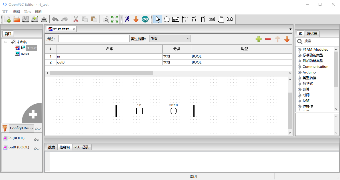
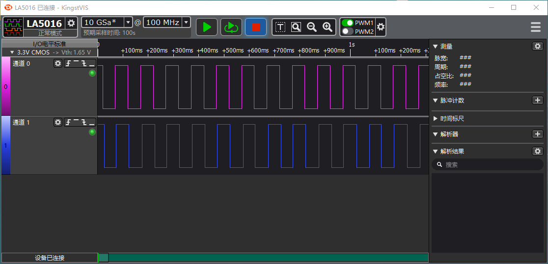
Delay between Input and Output Signals
Run the ladder diagram program as shown below on OpenPLC, and input PWM signals with frequency of 10Hz and duty ratio of 50% to the input port %IX0.2 through the logic analyzer. Meanwhile, detect the input signals %IX0.2 and output signals %QX0.0. Run it for a while, record the time delay between the rising/falling edges of the input and output signals and calculate the mean and standard errors: