Minimum Scanning Time
The real-time behavior of a PLC is usually associated with its scan time, which is the time the PLC takes to read all inputs, execute the logic program and write all outputs back. The execution of the logic program can normally be reduced to the evaluation of conditional statements and some arithmetic operations, most of the scan time is spent reading inputs and writing outputs. Therefore, the proposed scan time test is comprised of a single ladder logic line with one input and one output, as shown below:
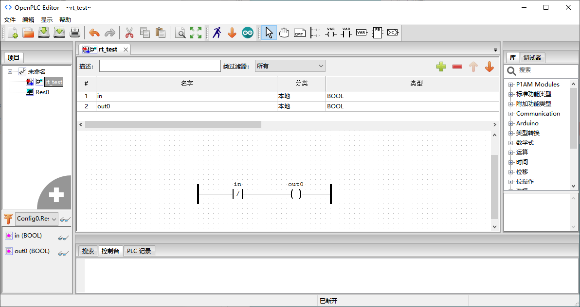
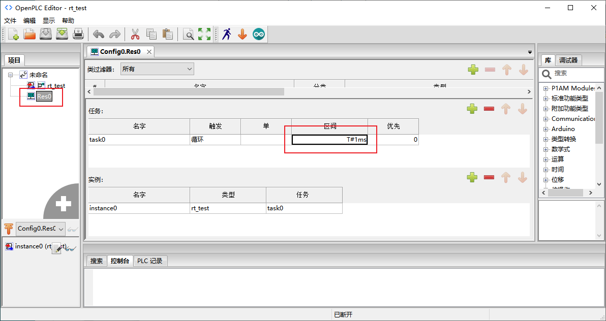
By running this program and physically wiring the output %QX0.0 and the input %IX0.2 on the PLC together, it is possible to create an oscillator. This oscillator outputs a square wave with the highest frequency the PLC can generate in software. Since the output toggles at every scan, the scan time is defined by equation , where f is the square wave frequency measured by an oscilloscope. In addition to the difference in the ladder diagram, to measure the minimum scan time, the program of the minimum scan time in the scan interval of the Res0 file is set to T#1ms, while in the delay test, it is T#5ms:
This method is referred to: Thiago Alves, Thomas Morris. OpenPLC: An IEC 61131-3 Compliant Open Source Industrial Controller for Cyber Security Research[J]. Computer & Security, 2018, 78:364-379.