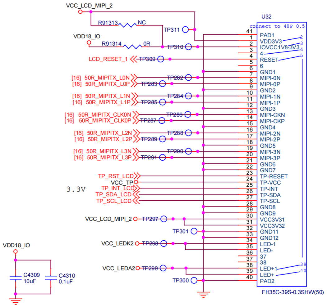
4-Lane MIPI DSI Pin Definition
The following figure and table describe the 4-lane MIPI DSI definition:
Note: The compatible model is CZ101B4001.
| PIN NO. | Pin Definition | Description | Voltage |
|---|---|---|---|
| 1 | VCC_LCD_MIPI_2 | Power Voltage for digital circuit 3.3 V | 3.3 V |
| 2 | VDD18_IO | Power Voltage for digital circuit 1.8 V Note 1 | 1.8 V |
| 3 | NC | No connection | - |
| 4 | LCD_RESET_1 | Global reset pin 1.8V Note 1 | 1.8 V |
| 5 | NC | No connection | - |
| 6 | GND | Ground | - |
| 7 | 50R_MIPITX_L0N | MIPI Output Lane 0 Negative | 1.8 V |
| 8 | 50R_MIPITX_L0P | MIPI Output Lane 0 Positive | 1.8 V |
| 9 | GND | Ground | - |
| 10 | 50R_MIPITX_L1N | MIPI Output Lane 1 Negative | 1.8 V |
| 11 | 50R_MIPITX_L1P | MIPI Output Lane 1 Positive | 1.8 V |
| 12 | GND | Ground | - |
| 13 | 50R_MIPITX_CLK0N | MIPI Output Clock 0 Negative | 1.8 V |
| 14 | 50R_MIPITX_CLK0P | MIPI Output Clock 0 Positive | 1.8 V |
| 15 | GND | Ground | - |
| 16 | 50R_MIPITX_L2N | MIPI Output Lane 2 Negative | 1.8 V |
| 17 | 50R_MIPITX_L2P | MIPI Output Lane 2 Positive | 1.8 V |
| 18 | GND | Ground | - |
| 19 | 50R_MIPITX_L3N | MIPI Output Lane 3 Negative | 1.8 V |
| 20 | 50R_MIPITX_L3P | MIPI Output Lane 3 Positive | 1.8 V |
| 21 | GND | Ground | - |
| 22 | GND | Ground | - |
| 23 | TP_RST_LCD | TP_RESET | 3.3 V |
| 24 | VCC_TP | TP_VCC | 3.3 V |
| 25 | TP_INT_LCD | TP_INT | 3.3 V |
| 26 | TP_SDA_LCD | TP_SDA | 3.3 V |
| 27 | TP_SCL_LCD | TP_SCL | 3.3 V |
| 28 | GND | Ground | - |
| 29 | GND | Ground | - |
| 30 | VCC_LCD_MIPI_2 | Power Voltage for digital circuit 3.3 V | 3.3 V |
| 31 | VCC_LCD_MIPI_2 | Power Voltage for digital circuit 3.3 V | 3.3 V |
| 32 | GND | Ground | - |
| 33 | GND | Ground | - |
| 34 | VCC_LEDK2 | LED Cathode | Up to 30 V. The adjustable output voltage can be controlled by MIPI_PWR_EN . The voltage is adjustable and the value depends on the backlight requirement. The voltage level of the 4-lane MIPI screen, which has been tuned by StarFive, VCC_LEDK2 ranges from 9 V to 10.5 V. |
| 35 | VCC_LEDK2 | LED Cathode | |
| 36 | NC | No connection | - |
| 37 | NC | No connection | - |
| 38 | VCC_LEDA2 | LED Anode | 0 V |
| 39 | VCC_LEDA2 | LED Anode | 0 V |
| 40 | PAD1 | The fixed pin to be connected to GND. | - |
| 41 | PAD2 | The fixed pin to be connected to GND. | - |