Using J-Link
Note: The solution is referenced from the RVspace Community, StarFive does not assume any
responsibility in it. If you encounter any issues after following the practices,
please contact the writer of the solution by replying to the thread for more
information.
Follow the steps below to use J-Link:
- The 40-pin GPIO on VisionFive 2 can be multiplexed into JTAG port.
- The official U-Boot file of StarFive has already configured the JTAG port, click this link to get the information.
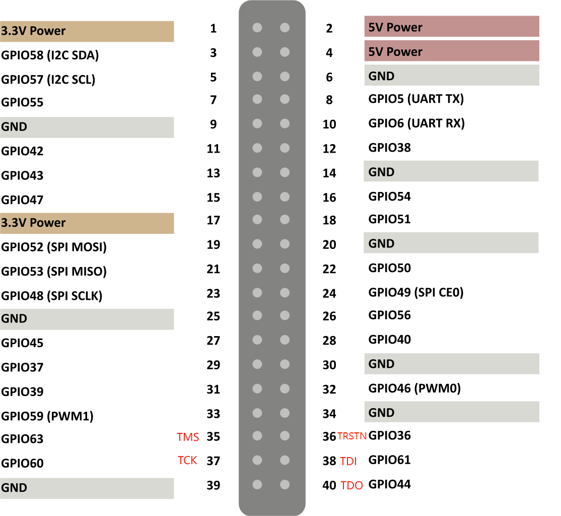
- The following is a diagram of the 40-pin GPIO corresponding to TDI, TDO, TMS,
TCK, and TRSTN:
Figure 1. Corresponding 40-pin GPIO  Tip: Below is a brief introduction for TDI, TDO, TMS, TCK, and TRSTN:
- Test Clock (TCK): Test Clock is used to synchronize operations on the JTAG port. By sampling and updating the data on the rising or falling edge of the TCK, the data on the JTAG port can be transmitted synchronously.
- Test Data Input (TDI): Test Data Input is a channel that sends data to the device under test. By inputting data for TDI on each clock cycle of TCK, the test data, instructions, or configuration information can be sent to the device under test.
- Test Data Output (TDO): Test Data Output is a channel that receives data from the device under test. By reading data from TDO on each clock cycle of the TCK, the test response, status information, or output data of the device under test can be obtained.
- Test Mode Select (TMS): Test Mode Select is to control the state machine transition of the JTAG. By entering different values for the TMS on each TCK clock cycle, the state of the JTAG can be changed, allowing different test or operation modes to be selected.
- Test Reset (TRSTN): The RSTN can be used to reset the TAPController.
- Click to download the latest J-Link debugger software Ozone, you can reference to J-Link RISC-V.
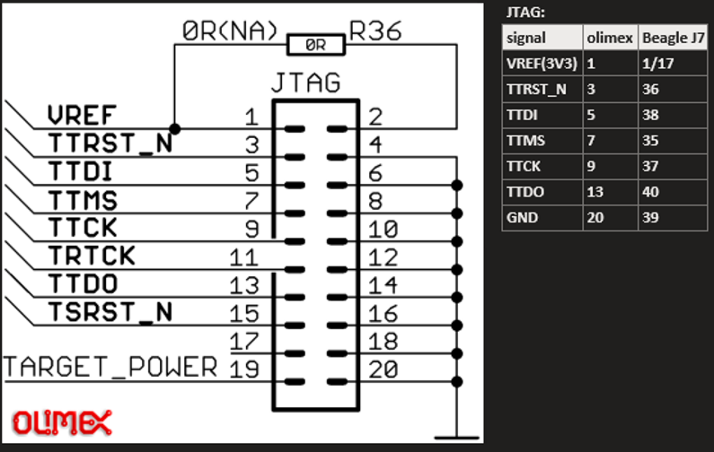
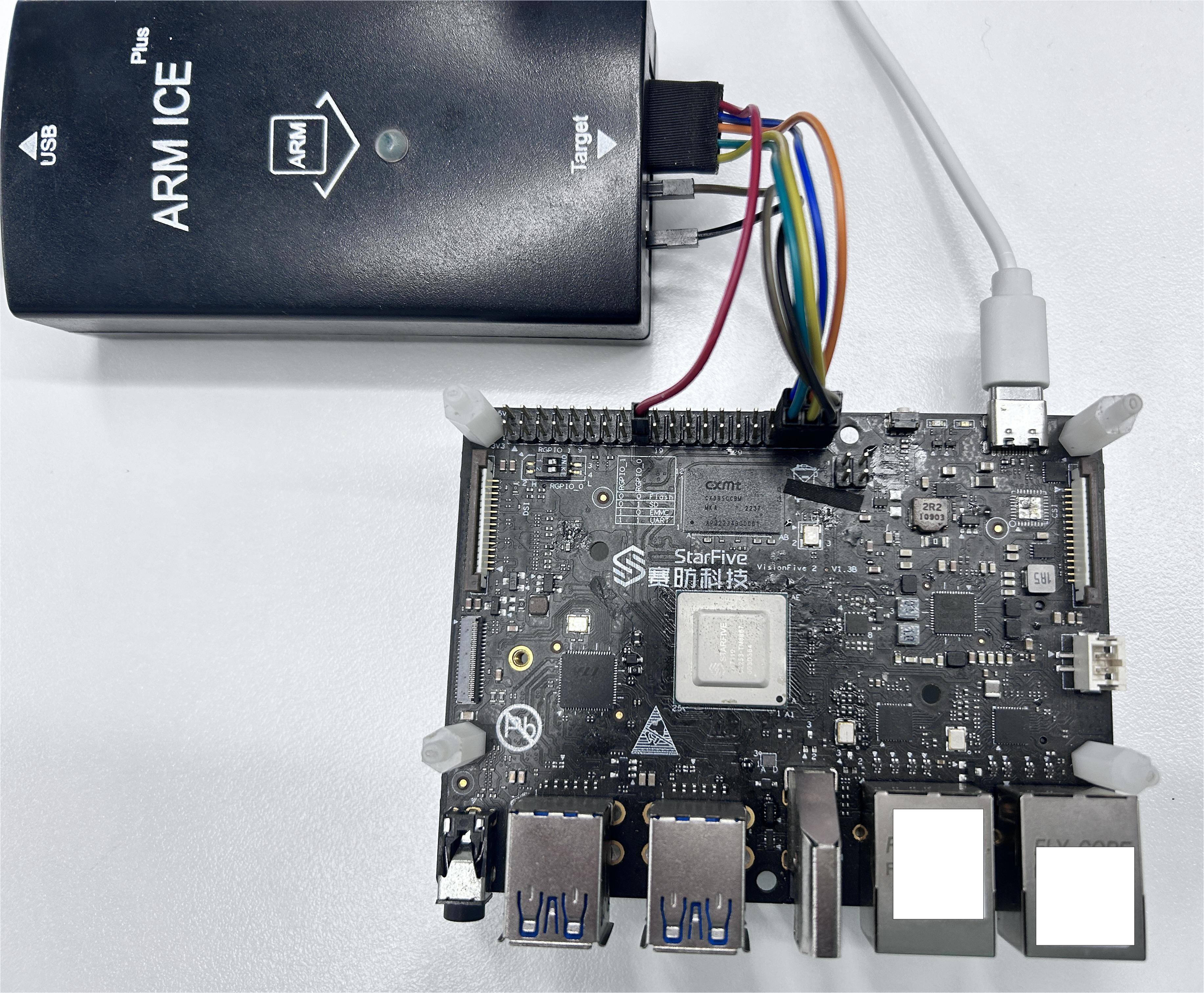
- Connect the Segger debugger into the following corresponding pins. The following
figures show the J-Link port schematics and connection diagram.
Figure 2. J-Link Schematics 
Figure 3. Connection Diagram  Note: If your PC cannot recognize the Segger debuger, please download and install the J-Link driver after connecting again.
 - Open Ozone, and creat a Project, choosing U74 or S76 under
Device, and then keep clicking Next until choose J-Link Script
File.
Figure 4. U74 
Figure 5. J-Link Script File  TAP0 is connected to S76 core while TAP1 is connected to U74 core, please choose the required file to download:
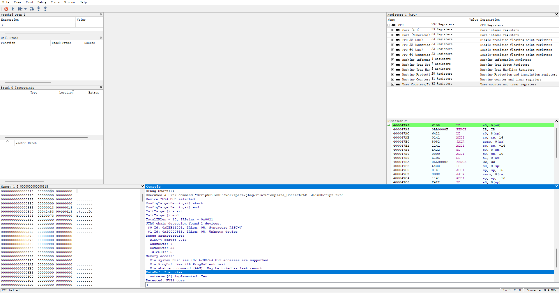
 - The output below means the devices is connected successfully.
Figure 6. Example Output 
