Standby and Wakeup
Block Diagram
Entering Standby Mode
-
CPU controls PMIC via I2C, with VDD18_HDMI, MIPITX, and MIPIRX powered off.
-
CPU controls PMIC or the power switches in MIPITX and RX via I2C, with DD09_MIPITX and MIPIRX powered off, to which either internal or external power supplies can be connected. When internal power supplies are fed, the 2 pins can be switched on and off independently.
-
CPU switches off all digital IP except for CPU itself and SYSTOP by configuring PMU power-down sequence.
-
To configure standby wakeup source registers, the following three wakeup methods are supported: Wake up via RTC, via GMAC0, and via GPIO3.
-
When the CPU switches off itself and SYSTOP by configuring the PMU power-down sequence, PMU could drag down or close the TOP power supplies (Orange pins in the figure: Power Up Sequence) via GPIO2.
Waking Up from Standby Mode
-
Wakeup via RTC: RTC automatically switches on CPU, SYSTOP, and the TOP power supplies (Orange pins in the figure: Power Up Sequence) by dragging up GPIO2. System will follow requirements to switch on other power supplies.
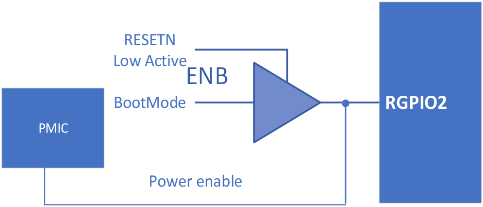
Note:-
The control signal from GPIO2 to PMIC is active only when RESETN is high, otherwise, the signal is de-activated.
-
Use PMU to control the ON/OFF of the PMIC, a low-EN 3-state switch can be added.
-
-
Wakeup via Remote Ethernet: The remote GMAC0 sends interrupts to PMU to wake up CPU, SYSTOP, and the TOP power supplies (Orange pins in the figure: Power Up Sequence) by dragging up GPIO2. System will follow requirements to switch on other power supplies.
-
Wakeup via GPIO: Press the button to initiate high-level pulses via GPIO3, and trigger PMU to wake up CPU, SYSTOP, and the TOP power supplies (Orange pins in the figure: Power Up Sequence) by dragging up GPIO2. System will follow requirements to switch on other power supplies.