Peripherals
GPIO
VisionFive 2 offers 40-Pin GPIO expansion which is compatible with most accessories on the market, supporting various interface options:
- 3.3 V (on 2 pins)
- 5 V (on 2 pins)
- Ground (on 8 pins)
- GPIO
- CAN bus
- DMIC
- I2C
- I2S
- PWM
- SPI
- UART
- and so on
The following table describes the GPIO pin assignments.
| Pin Name | Pin Num | Pin Num | Pin Name |
|---|---|---|---|
| +3.3V | 1 | 2 | +5V |
| GPIO58 (I2C SDA) | 3 | 4 | +5V |
| GPIO57 (I2C SCL) | 5 | 6 | GND |
| GPIO55 | 7 | 8 | GPIO5 (UART TX) |
| GND | 9 | 10 | GPIO6 (UART RX) |
| GPIO42 | 11 | 12 | GPIO38 |
| GPIO43 | 13 | 14 | GND |
| GPIO47 | 15 | 16 | GPIO54 |
| +3.3V | 17 | 18 | GPIO51 |
| GPIO52 (SPI MOSI) | 19 | 20 | GND |
| GPIO53 (SPI MISO) | 21 | 22 | GPIO50 |
| GPIO48 (SPI SCLK) | 23 | 24 | GPIO49 (SPI CE0) |
| GND | 25 | 26 | GPIO56 |
| GPIO45 | 27 | 28 | GPIO40 |
| GPIO37 | 29 | 30 | GND |
| GPIO39 | 31 | 32 | GPIO46 (PWM0) |
| GPIO59 (PWM1) | 33 | 34 | GND |
| GPIO63 | 35 | 36 | GPIO36 |
| GPIO60 | 37 | 38 | GPIO61 |
| GND | 39 | 40 | GPIO44 |
All GPIOs can be switched (multiplexed) to support different functions including but not limited to SDIO, Audio, DMIC, SPI, I2C, UART, PWM, and CAN bus. For detailed instructions, refer to the VisionFive 2 40-Pin GPIO Header User Guide (coming soon). The alternate peripheral functions are described in detail in the JH7110 Datasheet.
eMMC
VisionFive 2 offers a high speed eMMC socket for eMMC modules as OS and data storage. The eMMC socket is compatible with industrial commonly used pinout and form factor.
Camera and Display
- Camera
VisionFive 2 has 1 × 2-lane MIPI CSI camera port, supporting up to 1080p@30fps.
- Display
VisionFive 2 has the following interfaces for camera and display.
- 1 × 2-lane MIPI DSI display port, supporting up to 1080p
@30fps
For the pin definition, see 2-Lane MIPI DSI Pin Definition
- 1 × 4-lane MIPI DSI display port, supporting up to 2K @30fps in both
single display and dual display modes.
For the pin definition, see 4-Lane MIPI DSI Pin Definition.
-
1 × HDMI 2.0, supporting up to 4K @30fps or 2K @60fps
- 1 × 2-lane MIPI DSI display port, supporting up to 1080p
@30fps
2-Lane MIPI DSI Pin Definition
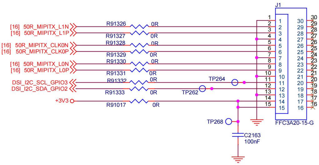
| No. | Definition | Description | Voltage |
|---|---|---|---|
| 1 | GND | Ground | - |
| 2 | 50R_MIPITX_L1N | MIPI Output Lane 1 Negative | 1.8 V |
| 3 | 50R_MIPITX_L1P | MIPI Output Lane 1 Positive | 1.8 V |
| 4 | GND | Ground | - |
| 5 | 50R_MIPITX_CLK0N | MIPI Output Clock 0 Negative | 1.8 V |
| 6 | 50R_MIPITX_CLK0P | MIPI Output Clock 0 Positive | 1.8 V |
| 7 | GND | Ground | - |
| 8 | 50R_MIPITX_L0N | MIPI Output Lane 0 Negative | 1.8 V |
| 9 | 50R_MIPITX_L0P | MIPI Output Lane 0 Positive | 1.8 V |
| 10 | GND | Ground | - |
| 11 | DSI_I2C_SCL_GPIO3 | DSI I2C SCL | 3.3 V |
| 12 | DSI_I2C_SDA_GPIO2 | DSI I2C SDA | 3.3 V |
| 13 | GND | Ground | - |
| 14 | +3.3 V | Power Voltage for digital circuit 3.3 V | 3.3 V |
| 15 | GND | GND | 1.8 V |
4-Lane MIPI DSI Pin Definition
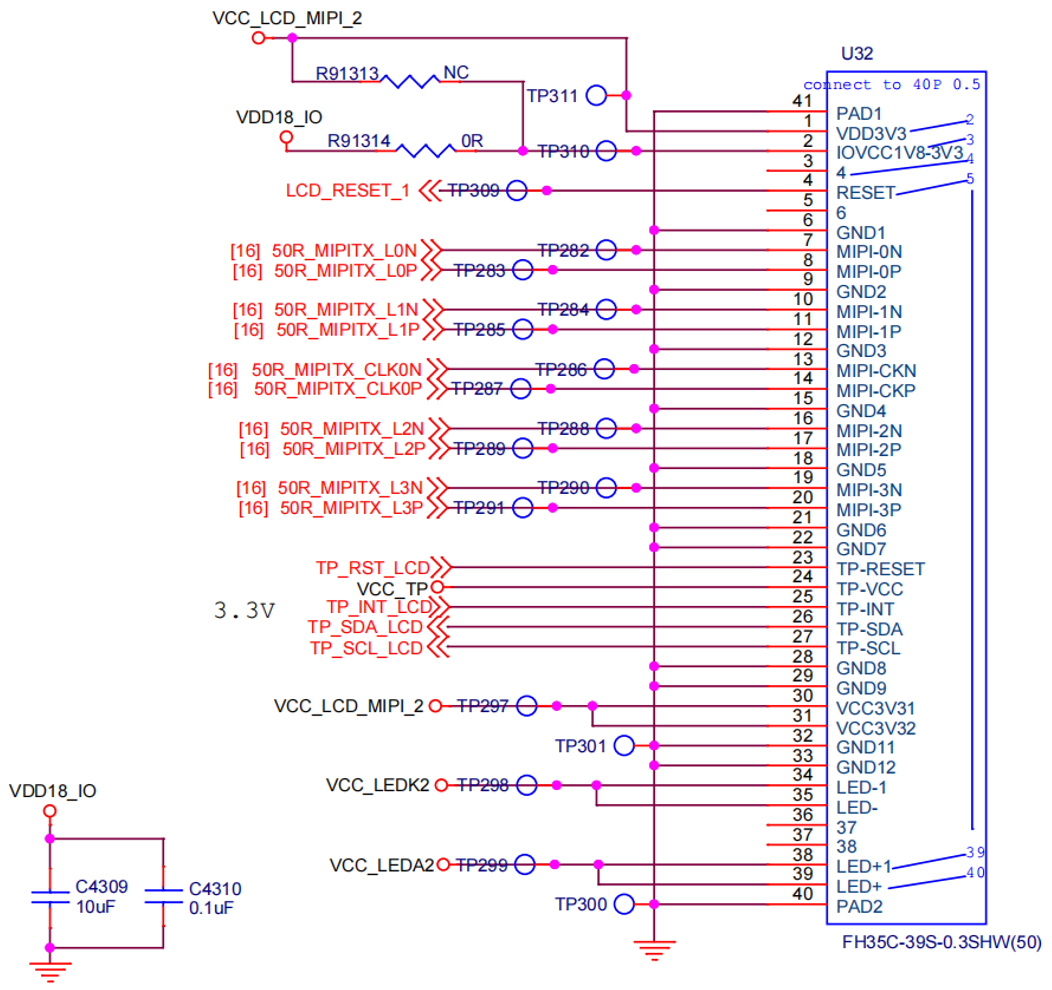
| PIN NO. | Pin Definition | Description | Voltage |
|---|---|---|---|
| 1 | VCC_LCD_MIPI_2 | Power Voltage for digital circuit 3.3 V | 3.3 V |
| 2 | VDD18_IO | Power Voltage for digital circuit 1.8 V Note 1 | 1.8 V |
| 3 | NC | No connection | - |
| 4 | LCD_RESET_1 | Global reset pin 1.8V Note 1 | 1.8 V |
| 5 | NC | No connection | - |
| 6 | GND | Ground | - |
| 7 | 50R_MIPITX_L0N | MIPI Output Lane 0 Negative | 1.8 V |
| 8 | 50R_MIPITX_L0P | MIPI Output Lane 0 Positive | 1.8 V |
| 9 | GND | Ground | - |
| 10 | 50R_MIPITX_L1N | MIPI Output Lane 1 Negative | 1.8 V |
| 11 | 50R_MIPITX_L1P | MIPI Output Lane 1 Positive | 1.8 V |
| 12 | GND | Ground | - |
| 13 | 50R_MIPITX_CLK0N | MIPI Output Clock 0 Negative | 1.8 V |
| 14 | 50R_MIPITX_CLK0P | MIPI Output Clock 0 Positive | 1.8 V |
| 15 | GND | Ground | - |
| 16 | 50R_MIPITX_L2N | MIPI Output Lane 2 Negative | 1.8 V |
| 17 | 50R_MIPITX_L2P | MIPI Output Lane 2 Positive | 1.8 V |
| 18 | GND | Ground | - |
| 19 | 50R_MIPITX_L3N | MIPI Output Lane 3 Negative | 1.8 V |
| 20 | 50R_MIPITX_L3P | MIPI Output Lane 3 Positive | 1.8 V |
| 21 | GND | Ground | - |
| 22 | GND | Ground | - |
| 23 | TP_RST_LCD | TP_RESET | 3.3 V |
| 24 | VCC_TP | TP_VCC | 3.3 V |
| 25 | TP_INT_LCD | TP_INT | 3.3 V |
| 26 | TP_SDA_LCD | TP_SDA | 3.3 V |
| 27 | TP_SCL_LCD | TP_SCL | 3.3 V |
| 28 | GND | Ground | - |
| 29 | GND | Ground | - |
| 30 | VCC_LCD_MIPI_2 | Power Voltage for digital circuit 3.3 V | 3.3 V |
| 31 | VCC_LCD_MIPI_2 | Power Voltage for digital circuit 3.3 V | 3.3 V |
| 32 | GND | Ground | - |
| 33 | GND | Ground | - |
| 34 | VCC_LEDK2 | LED Cathode |
Up to 30 V. The adjustable output voltage can be controlled by MIPI_PWR_EN . The voltage is adjustable and the value depends on the backlight requirement. The voltage level of the 4-lane MIPI screen, which has been tuned by StarFive VCC_LEDK2, ranges from 9 V to 10.5 V. |
| 35 | VCC_LEDK2 | LED Cathode | |
| 36 | NC | No connection | - |
| 37 | NC | No connection | - |
| 38 | VCC_LEDA2 | LED Anode | 0 V |
| 39 | VCC_LEDA2 | LED Anode | 0 V |
| 40 | PAD1 | The fixed pin to be connected to GND. | - |
| 41 | PAD2 | The fixed pin to be connected to GND. | - |
USB Host
VisionFive 2 has 4 × USB 3.0 ports (multiplexed with a PCIe 2.0 1x lane).
USB Device Port
VisionFive 2 has 1 × USB device port by reusing the USB-C port.
HDMI
VisionFive 2 has 1 × HDMI port, supporting HDMI 2.0 with resolutions up to 4K@30fps or 2K@60fps.
Audio Jack
VisionFive 2 supports analog audio output via a 4-ring 3.5 mm headphone jack.
M.2 Connector
VisionFive 2 offers an M.2 M-Key SSD socket with 1 × PCIe 2.0 interfaces, providing high speed storage access.
Gigabit Ethernet Port
VisionFive 2 has 2 × RJ45 Gigabit Ethernet ports.
Boot Mode Pins
VisionFive 2 provides pins to determine the boot mode before it is powered up. The following are the available boot modes:
- 1-bit QSPI Nor Flash
- SDIO3.0
- eMMC
- UART
4-Pin PoE Header
VisionFive 2 provides Power over Ethernet (PoE) function. PoE carries electrical power through data cables, and reduces the cabling requirements for network devices. You can use this function by adding a separate PoE HAT out of our product package.
Fan Header
VisionFive 2 has a 2-pin fan header. You can connect a 2-pin 5 V fan to the board if needed.
Button
VisionFive 2 provides 1 Reset button.
Temperature Range and Thermals
The recommended ambient operating temperature range is 0 to 50 degrees Celcius.
To reduce thermal output when idling or under light load, VisionFive 2 reduces the CPU clock speed and voltage. During heavier load, the speed and voltage (and hence thermal output) are increased. The internal governor will throttle back both the CPU speed and voltage to make sure the CPU temperature never exceeds 85 degrees C.
VisionFive 2 will operates well without any extra cooling and is designed for sprint performance, expecting a light use case on average and ramping up the CPU speed when needed (for example, when loading a webpage). If you want to load the system continually or operate it at a high temperature at full performance, further cooling may be needed.