Basic digital I/O & Analog Output Test
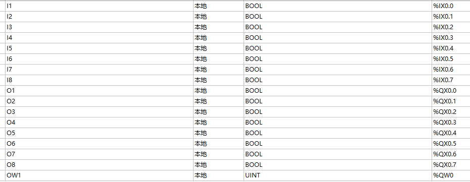
The OpenPLC hardware layer file for VisionFive 2 or VisionFive 2 Lite defines 14 digital outputs, 11 digital inputs, and 1 analog output, the basic functions need to be verified. The figure below shows the ladder diagram program and the address of each input/output point.
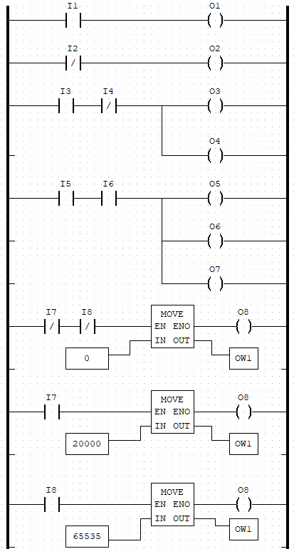
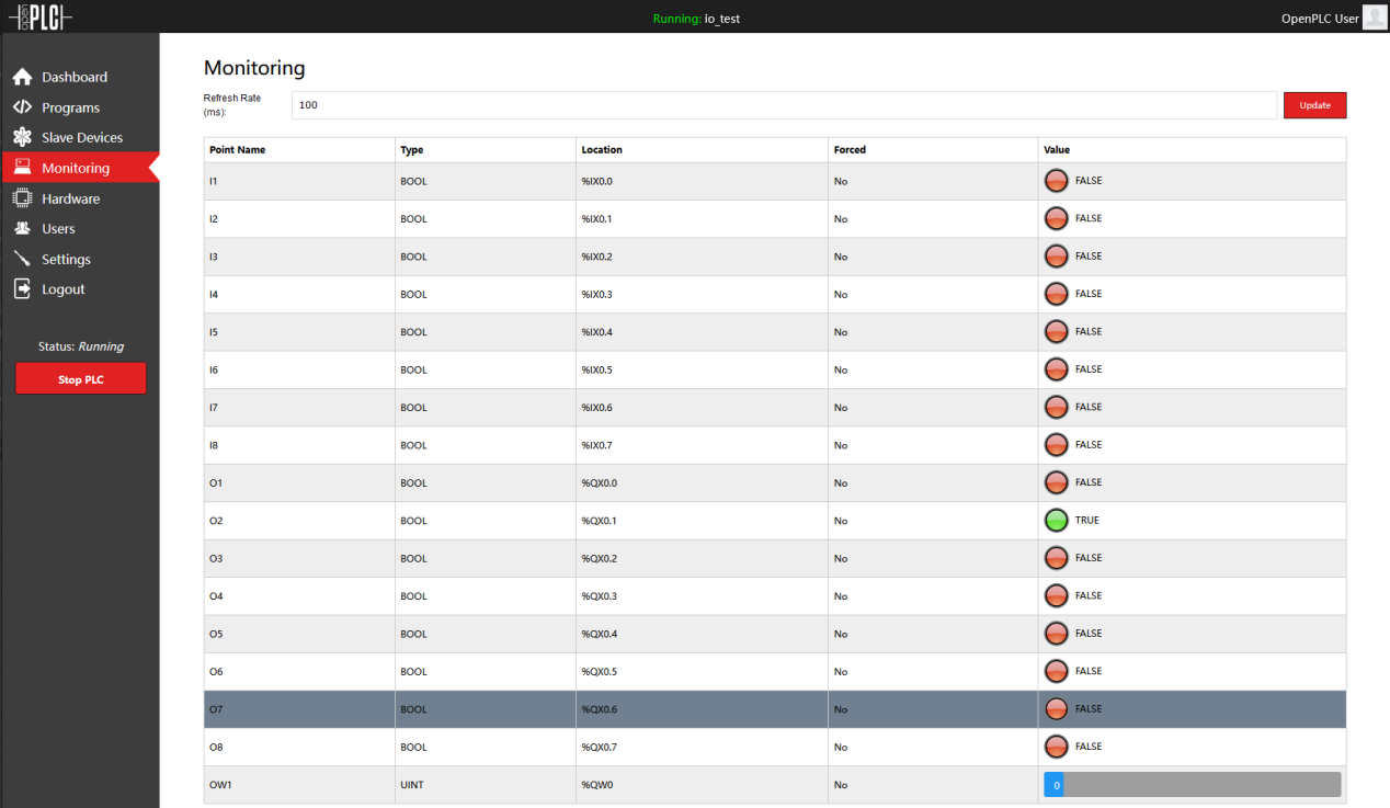
In the first two lines of this Ladder diagram program, I1, I2, and O1, O2 were tested for positive and negative logic switches. I3, I4, O3, O4, and I5, O5, O6, and O7 are tested for serial and parallel logic respectively. In the last three lines of the ladder diagram, the analog output of OpenPLC is tested based on I7, I8, and O8, and the DC motor drive and speed governing are realized through the DC motor drive board (L298N). The connection of Led, resistance, button, and Dupont is omitted here. The connection of the DC motor and L298N can see in Temperature Control. The status of I/O points can be viewed on the HMI as shown in the following figure: