Build a Real-Time GUI Scada/HMI Dashboard
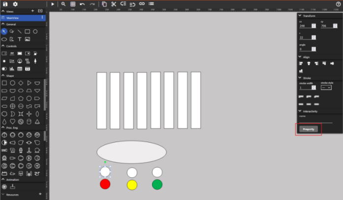
Click the option in the lower left corner to enter the Editor interface. The PLC program used in this document is traffic light control, so the HMI of the traffic light scene is drawn. The drawing process is omitted here, and the main interface is as follows, describing how to connect the input and output points.
First, edit the circular space Property that serves as the traffic light, taking the white circular control that indicates the red light is off as an example:
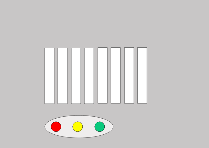
Select Actions, this PLC program traffic light has two states: on and off, so need to add another action. Bind both Actions with O_LEDRed point and set Bitmask to 0, which only has two values of 0/1. Therefore, set the Min and Max of the two actions to 0/0 and 1/1, and select Type Hide and Show to indicate that the white component will be displayed when O_LEDRed is 0. When O_LEDRed is 1, this component is hidden, and then the red circle component is set to the opposite logic, and the logic of yellow and green is set. After editing, the following figure is shown:
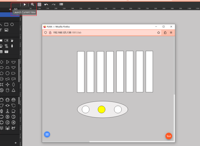
You can also preview this interface from the Launch Current View in the upper left corner:
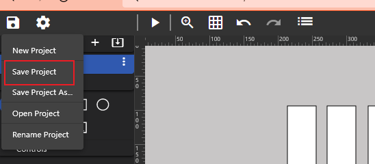
If satisfied, click the icon on the upper left corner to save the project:
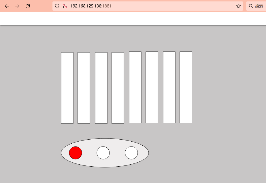
Then login to the 192.168.125.138:1881/ to display the SCADA interface and display the situation of each point: