Hardware Overview
This section provides the hardware overview of VisionFive 2 Lite.
Board Appearance
The following figures illustrate the top and bottom views of the board.
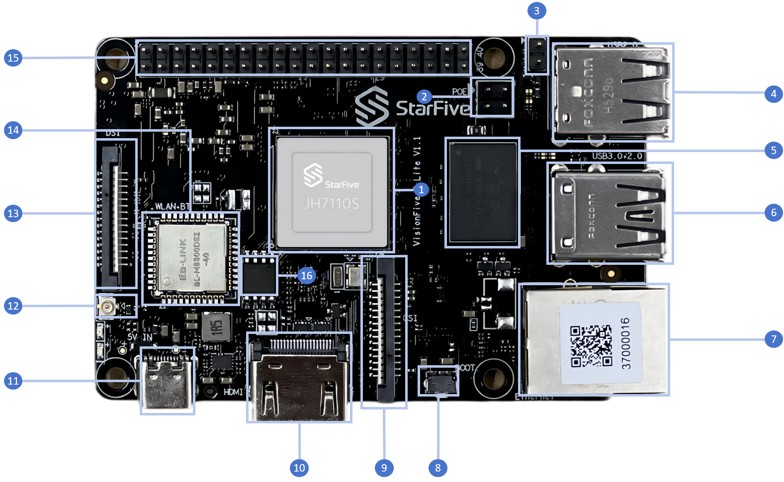
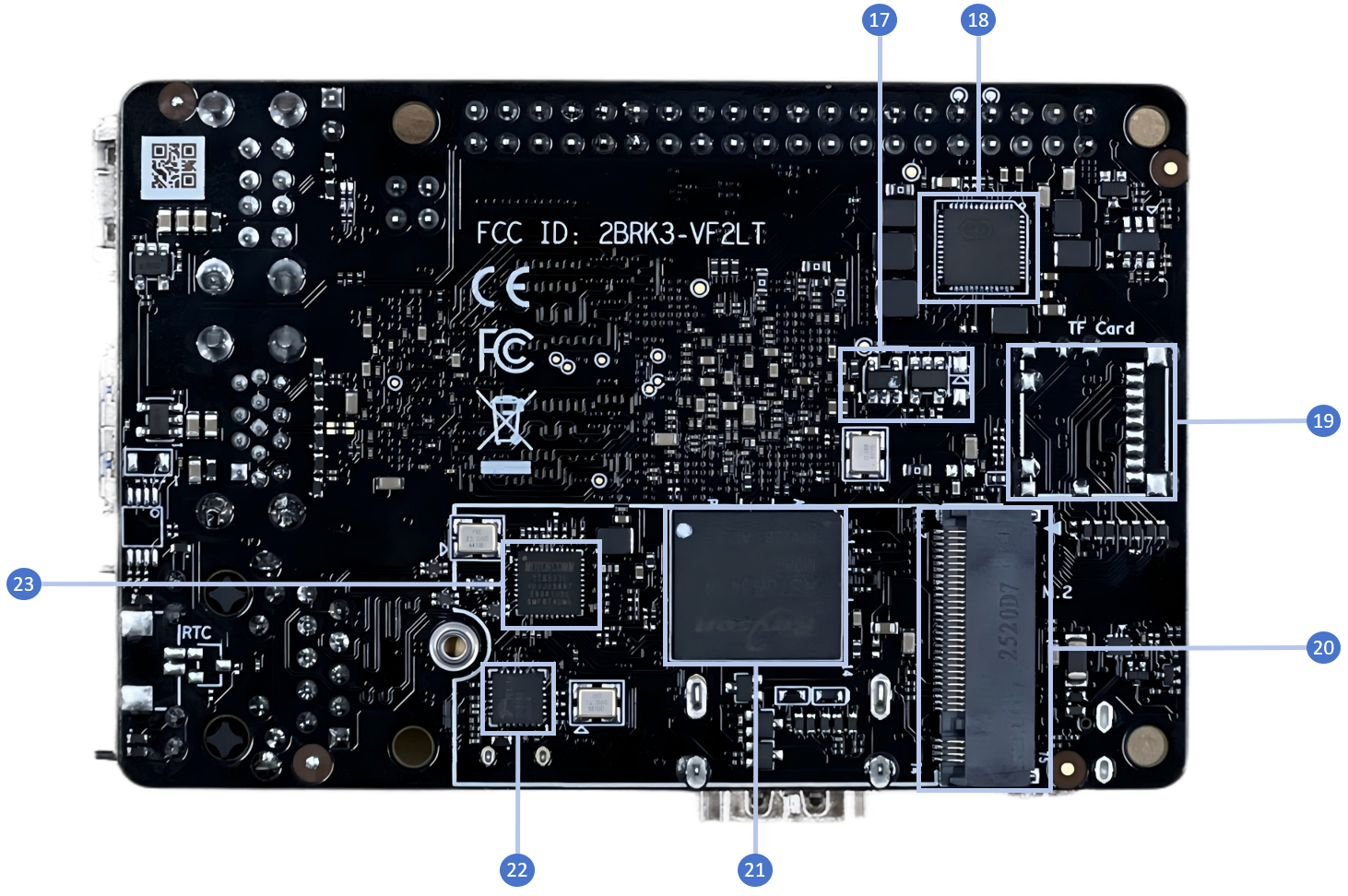
See the following table for the board details.
| No. | Description | No. | Description |
|---|---|---|---|
| 1 | StarFive JH-7110S with RISC-V quad-core CPU, supporting RV64GC ISA | 12 | 2.4G/5.8GHz Antenna Connector |
| 2 | PoE Header | 13 | 2-Lane MIPI DSI |
| 3 | Fastboot pins1 | 14 | WiFi/BT module |
| 4 | 2× USB 2.0 Port | 15 | 40-Pin GPIO Header |
| 5 | 2GB/4GB/8GB LPDDR4 SDRAM | 16 | QSPI Flash |
| 6 | 1× USB 3.0 Port and 1×USB 2.0 Port | 17 | EEPROM |
| 7 | 1× Ethernet Port (RJ45) | 18 | PMIC |
| 8 | Recovery Button | 19 | TF card slot (TF version) |
| 9 | 2-Lane MIPI CSI | 20 | M.2 M key |
| 10 | HDMI 2.0 Port | 21 | Onboard eMMC (eMMC version) |
| 11 | USB Type C | 22 | USB2.0 Hub FE1.1S |
| - | - | 23 | GMAC0 PHY |
Pinout Diagram
The following is the pinout diagram:

Note:
- Each GPIO pin can safely draw a maximum current of 32 mA, whereas the maximum current draw when all GPIOs are combined should be less than 100 mA. Please take this into account or otherwise, you will end up destroying the GPIO pins.
- All GPIOs can be configured to support different functions including but not limited to SDIO, Audio, SPI, I2C, UART, and PWM. Since VisionFive 2 Lite uses the same GPIO header as VisionFive 2, refer to the VisionFive 2 40-Pin GPIO Header User Guide for GPIO configuration.
1 Short these pins before powering on the
board to force entry to the U-Boot Fastboot mode on
startup.