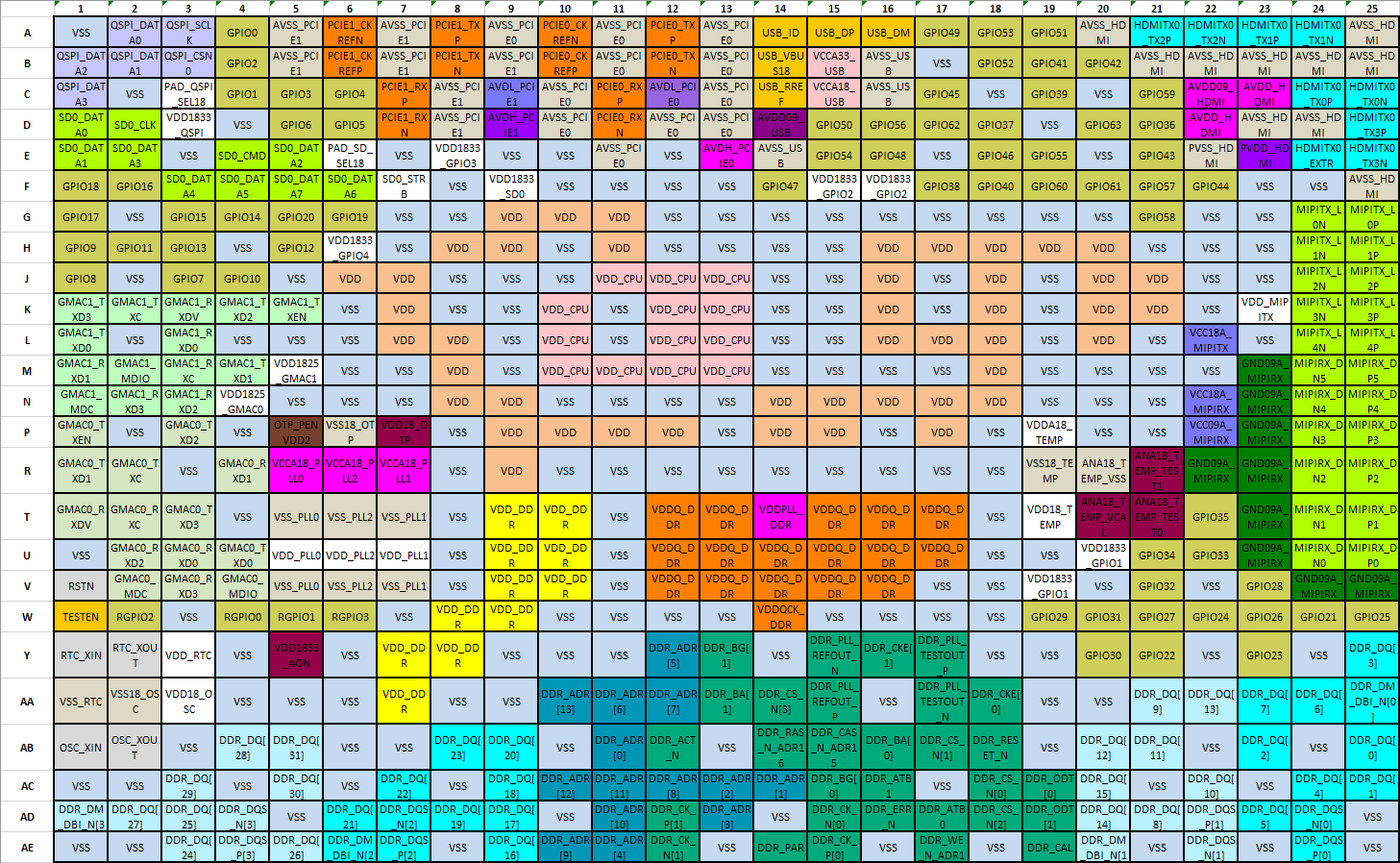
The following figure provides a general view of the pins and their corresponding signal
names, for more detailed information, see Pin List.
In the figure, a letter on the left edge from “A” to “AE” and a number on the top edge
from “1” to “25” are used together to indicate a pin location. For example, A1 = “VSS”,
A2 = “QSPI_DATA0”, and so forth.Figure 1. Pin Map