Test program
Prepare two pieces of VisionFive 2 or VisionFive 2 Lite in the same network segment with OpenPLC runtime, and opload the PLC ladder diagram program into the main device. The function of the test program is to flash the corresponding LED light when the key switch is pressed, and set different flashing frequencies for the two LEDs:
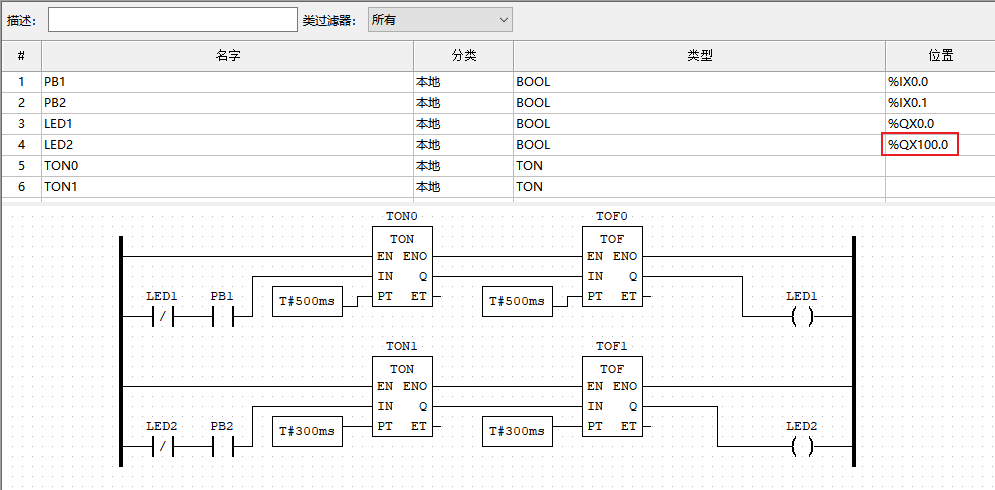
It should be noted that the I/O point starting address of the slave device is mapped to 100.0 in a master device (eg. The starting address of digital output is %QX0.0 in the slave device, and it’s mapped as %QX100.0 in the master device.
Ladder diagram program is located in your computer after you download and unzipped the openplc.zip,for example: C:\Users\chloe.chen\Downloads\openplc\5.3 Connect slave device.zip.