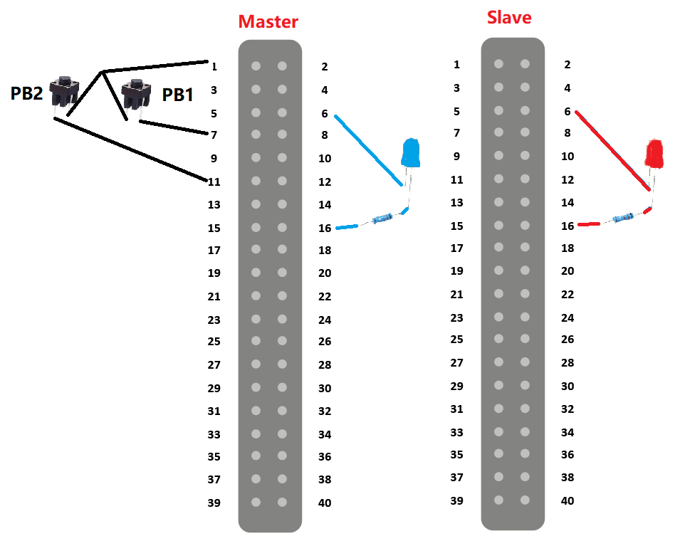
Hardware circuit:
As shown in the figure below, two pieces of VisionFive 2 or VisionFive 2 Lite are selected as the Modbus-TCP master/slave devices respectively. The button that controls the blue/red led flashing is connected to %IX0.0 and %IX0.1 of the master device, the blue led is connected to %QX0.0 of the master device, and the red led is connected to %QX0.0 of the slave device, which is %QX100.0 of the master device. There is no electrical connection between the master and slave devices.
Verification
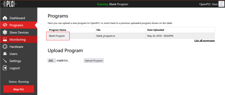
When running as a Modbus-TCP slave, the slave device must run the default Blank Program:
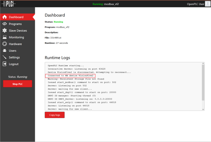
After confirming the ladder diagram program to be launched by the main device and the configurations of the slave device is correct, click Start PLC to start the OpenPLC runtime. It can be seen that the prompt of successful Modbus-TCP device connection appears in the Runtime Logs:
Then, press the button that controls the red led blinking and check whether the red light starts to blink to determine whether the master and slave devices communicate properly.