SPI Driver
-
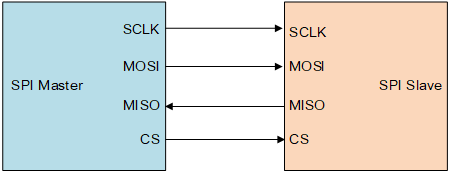
MOSI: Master Output, Slave Input. The master device transmits data to the slave device through this line.
-
MISO: Master Input, Slave Output. The slave device sends feedback data back to the master device through this line.
-
SCLK: Serial Clock. It serves as the clock signal line. The master device generates clock signals to the slave device.
-
CS: Slave Select. It is also called SS, CSB, CSN, or EN. Controlled by the master device, it specifies which slave device to communicate with. Only the selected slave will respond to the master's signals.
The SPI works in master-slave mode and usually has one master and one or more slaves. The communication is initiated by the master device. The master device selects the slave device through CS, and then provides a clock signal to the slave device through SCLK. The data is sent to the slave device through MOSI and the feedback data is sent back by the slave device to the master device through MISO.
The RTOS contains a test program for testing flash device through the SPI bus, which is located at rtthread/bsp/starfive/jh7110/applications/spi_test.c.
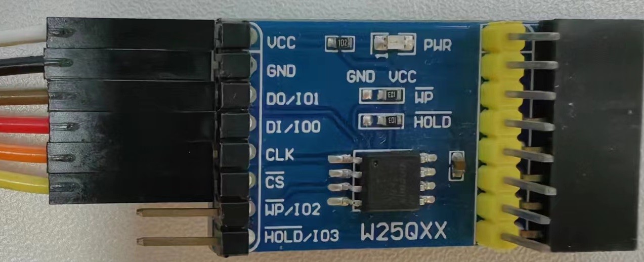
Test result: Read the SPI Flash ID and perform erasing, writing, and reading operations. Compare the written data with the read data to ensure consistency.