System PLL
JH-7110 system includes 3 PLLs, and the REFCLK is 24 MHz from external crystal.
The PLL clock frequency block diagram is shown in the following diagram.
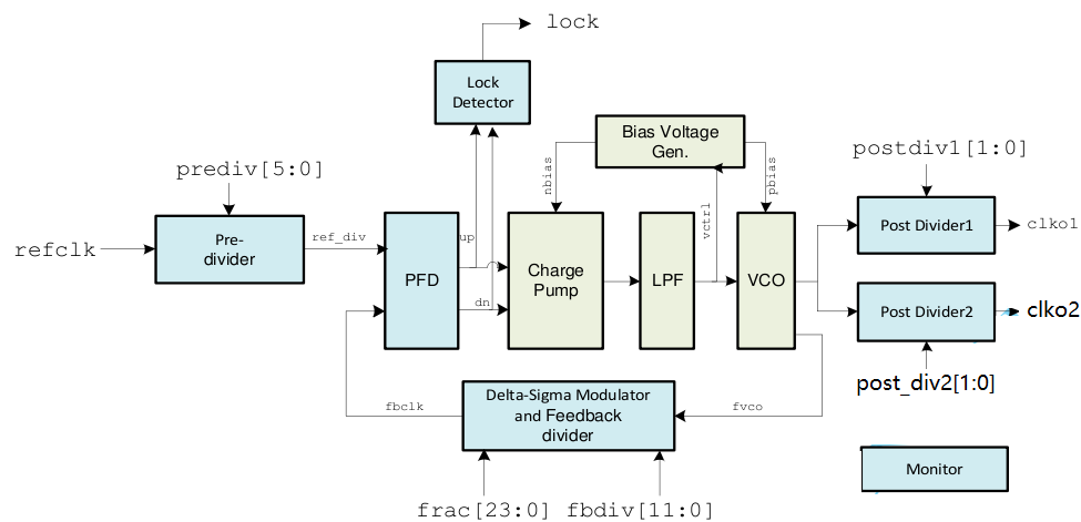
PLL supports integer and fraction multiple, you should set dacpd and dsmpd to high while integer multiple mode, and set both them to low while fraction multiple mode.
Inter Multiple Mode
Both dacpd and dsmpd should be set as 1 while integer multiple mode.
The frequency of outputs can be figured out as below.
Fvco = Fref × NI ÷ M
NI is integer frequency dividing ratio of feedback divider, set by fbdiv[1:0] , NI = 8, 9, 10, 12, 13, …, 4095
M is frequency dividing ratio of pre-divider, set by prediv[5:0], M = 1, 2, …, 63
Fclkol = Fvco ÷ Ql
Q1 is frequency dividing ratio of post divider, set by postdiv[l:0], Ql = 1, 2, 4, 8
Fclko2 = Fvco ÷ Q2
Q2 is frequency dividing ratio of post divider, set by postdiv2[l:0], Q2= 1, 2, 4, 8
Fraction Multiple Mode
Both dacpd and dsmpd should be set as 0 while integer multiple mode.
Fvco = Fref × (NI+NF)÷M
NI is integer frequency dividing ratio of feedback divider, set by fbdivf 11:0] , NI = 8, 9, 10, 12, 13, …, 4095
NF is fractional frequency dividing ratio, set by frac[0:23]. NF =frac[0:23]/2⌃24 = 0 - 0.99999994
M is frequency dividing ratio of pre-divider, set by prediv[5:0], M = 1, 2, …, 63
Fclkol = Fvco ÷ Ql
QI is frequency dividing ratio of post divider, set by postdivl [1:0],Q1 = 1, 2, 4, 8
Fclko2 = Fvco ÷ Q2
Q2 is frequency dividing ratio of post divider, set by postdiv2[1:0],Q2= 1, 2, 4, 8