Verification
- Communication between Linux and RT-Thread via RPMsg Protocol
- RT-Thread drivers
- Performance
Inter-processor Communication (RPMg)
Verify RPMsg (Remote Processor Messaging) communication between Linux and RT-Thread domains.
- Boot AMP system (Linux on 3 cores + RT-Thread on 1 core)
- Connect to both Linux console (UART0) and RT-Thread console (UART2)
- Flash
sdcard_amp.imgto SD card
- Power on: RT-Thread starts first and waits at the main program for an IPI interrupt from Linux.
- Linux boots and registers virtio_rpmsg_bus and starfive_rpmsg drivers register, and then send an IPI interrupt to RT-Thread.
- RT-thread receives the interrupt and continues execution.
- Verify IP interrupts are
counted:
# On Linux console
cat /proc/interrupts
Figure 1. IPI Interrupt Verification Example 
- Run the echo test program
rpmsg_echo:# On Linux console rpmsg_echoRVspace provides the compiled applications and source code. This application sends a string to the remote side of RPMsg, After receiving it, RT-Thread sends the received string back to Linux, and the test result is shown below:Figure 2. rpmsg_echo Test Result 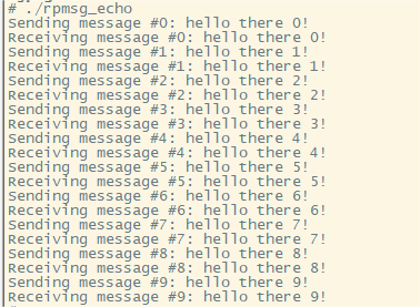
GPIO Driver
Verify GPIO pin control (input/output) and GPIO interrupt functionality.
- Connect to RT-Thread console (UART2)
- Use GPIO47 as test pin
Verification - GPIO Control
# Set GPIO47 as output
pin mode 47 output

# Write low level
pin write 47 low
pin read 47
# Output: pin[47] = low

# Write high level
pin write 47 high
pin read 47
# Output: pin[47] = high
Verification - GPIO Control
Only one GPIO interrupt resource exists on JH-7110. Since Linux uses it in the default SDK configuration, RT-Thread does not enable GPIO interrupt by default. To activate it, enable BSP_USING_GPIO in the RT-Thread menuconfig.
GMAC Driver
Verify Ethernet connectivity using GMAC1 (assigned to RT-Thread in AMP configuration) with lwIP TCP/IP stack.
- Ethernet cable to the GMAC1 port
- Boot AMP system
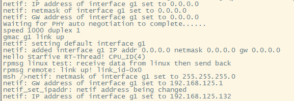
- RT-Thread initializes GMAC driver during boot.
- GMAC driver registers with lwIP TCP/IP stack.
- DHCP client starts automatically.
- IP address is obtained from DHCP server.
- Test network
connectivity:
# On RT-Thread console
ping www.baidu.com
- Check network interface
status:
ifconfig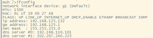
PCIe Driver
UART Driver
Verify UART communication and console functionality.
- Connect to RT-Thread console (UART2, 115200 baud)
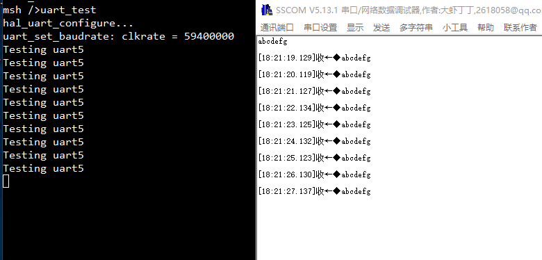
- For UART5 test: connect PC serial debugging assistant to UART5
Verification Process:
- Console Output: After connecting and debugging the serial port, display the
system output content and interact with the input commands. For example, enter the command
psto display the currently running threads of the system.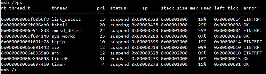
- UART5 Test: RT-Thread sends a string every second via UART5 and the debugging
assistant receives that string.
I2C Driver
Verify I2C bus communication with external devices.
- Connect Sense HAT to VisionFive 2 via 40-pin GPIO header. For example:
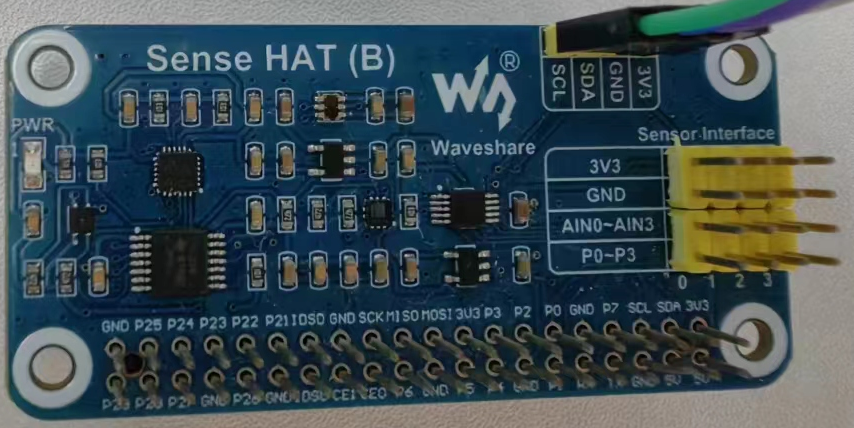
- I2C pins used: GPIO2 (SDA) and GPIO3 (SCL)
rtthread/bsp/starfive/jh7110/applications/i2c_test.c- Connect Sense HAT to VF2 board.
- Run I2C test program on RT-Thread console.
- Program reads Sense HAT device ID via I2C bus.
SPI Driver
Verify SPI bus communication with Flash device.
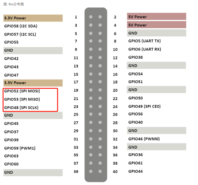
- Connect SPI Flash module to VisionFive 2 via GPIO header
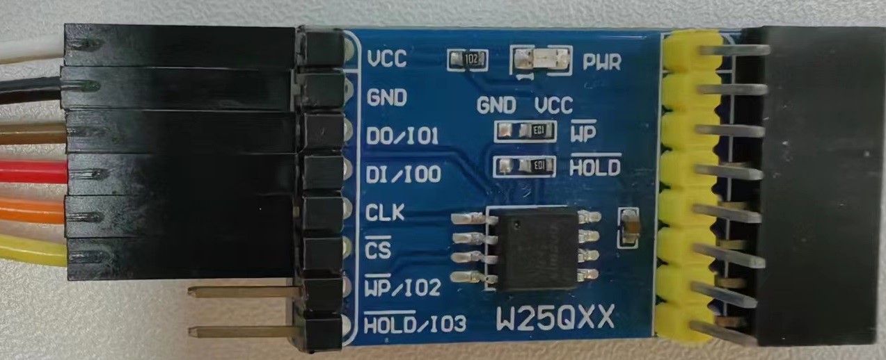
- SPI pins: MOSI, MISO, SCLK
rtthread/bsp/starfive/jh7110/applications/spi_test.c- Connect SPI Flash to VF2 board.
- Run SPI test program.
- Program reads Flash ID, performs erase/write/read operations.
- Compares written and read data.
QSPI Driver
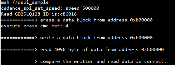
Verify QSPI Flash read/write operations.
rtthread/bsp/starfive/jh7110/applications/qspi_test.c- Run QSPI test program on RT-Thread console.
- Program accesses QSPI Flash device on VisonnFive 2.
- Performs erase, write, and read operations.
- Compares written and read data.
PWM Driver
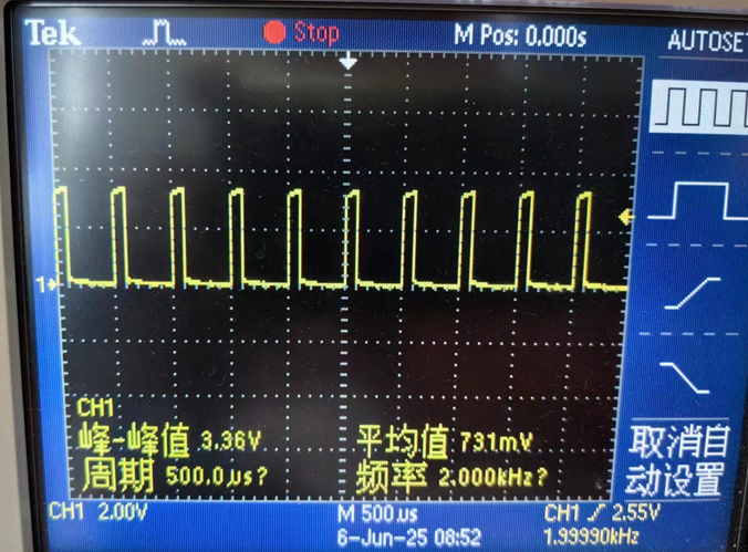
Verify PWM signal generation with configurable period and duty cycle.
rtthread/bsp/starfive/jh7110/applications/pwm_test.c- Run PWM test program on RT-Thread console.
- The test program sets the PWM duty cycle.

- Measure PWM signal with oscilloscope.
Timer Driver
Access the hardware timer device via the I/O device management interface provided by RT-Thread.
rtthread/bsp/starfive/jh7110/applications/timer_test.c- Run the timer test program.
- Set the timer timeout to 1 second and 10 microseconds.
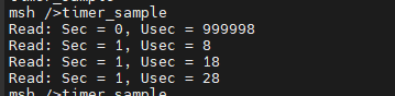
- Timer callback function is invoked at each timeout.
Watchdog Driver
Verify watchdog timer reset functionality.
rtthread/bsp/starfive/libraries/driver/drv_wdt.c- Run the watchdog test program
- Start the watchdog device and set the timeout value to 1 second.
- Feed the dog within 1 second to prevent reset.
RTC Driver
A RTC (Real-Time Clock) provides accurate real-time clock time, which can be used to generate information such as year, month, day, hour, minute, and second. Verify the RTC time setting and reading.
rtthread/bsp/starfive/libraries/driver/drv_rtc.c- Run the RTC test program.
- Set the current time to a specific value, for example, 2025-05-19 13:29:35.
- Wait for 1 second.
- Read the current time from the RTC.
Temperature Sensor Driver
Verify the reading of the current CPU temperature.
rtthread/bsp/starfive/libraries/driver/drv_tempsensor.c- Run the temperature sensor test program.
- Read the CPU temperature.
- Press your finger on the CPU and run the program to see the temperature change.
TRNG Driver
Verify hardware random number generation in three modes.
rtthread/bsp/starfive/libraries/driver/drv_trng.c- Run the TRNG test program.
- Test generates random numbers in three modes:
- Interrupt mode: Triggers an interrupt once random number generation is complete.
- Polling mode: Queries status register to retrieve data.
- Nonce mode: Outputs 32-bit random numbers in batch.
SDIO Driver
The JH-7110 SoC is equipped with two SDIO interfaces. By default, SDIO0 is used for eMMC, while SDIO1 is reserved for SD cards or peripherals such as Wi-Fi. On the RT-Thread side, SDIO1 is the interface in use.
- rtthread/bsp/starfive/libraries/driver/drv_sdmmc.c
- rtthread/bsp/starfive/libraries/hal/sdmmc
| Operation | Command | Description |
|---|---|---|
| Mount SD card to root directory | # mount SDIO1 / elm |
Mounts the SD card to the root directory. |
| Unmount SD card | # umount / |
Unmounts the SD card from the root directory. |
| Copy file to SD card | # cd # echo “12345”
test.txt/ |
Navigates to the root directory, and then creates a file
test.txt with content "12345" (saves to the
mounted SD card). |
| Delete file from SD card | # cd /# rm test.txt
|
Navigates to the root directory, and then deletes the
test.txt file from the SD card. |
| Create sub-directory | # cd /
# mkdir mnt |
Navigates to the root directory, then creates a subdirectory
mnton the SD card. Successful execution
confirms normal device mount/unmount and read/write
functions. |
| Format SD card as FATFS | # mkfs -t elm SDIO1 |
Formats the SD card to the FATFS file system. Execution duration varies based on the SD card’s capacity and speed class. |
CAN Driver
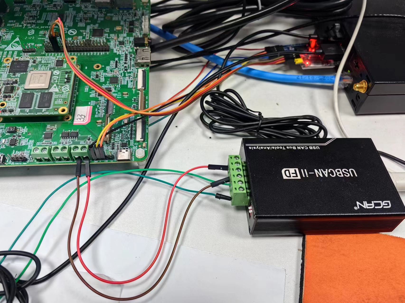
The VisionFive 2 board does not have a CAN transceiver. This test must be performed on the DevKit board.
- Connect a USB-CAN device to CANO on the DevKit board. For example:
- GCAN Tools software on PC
Test Program Location:
- rtthread/bsp/starfive/libraries/driver/drv_can.c
- rtthread/bsp/starfive/libraries/hal/can/
- rtthread/bsp/starfive/jh7110/applications/can_test.c
- Connect the USB-CAN adapter to PC.
- Connect CAN0 on the DevKit board to the USB-CAN adapter.
- Run the CAN test program on the RT-Thread console.
- Use the GCAN Tools on PC to send data frame via CAN bus.
Figure 3. GCAN Tools 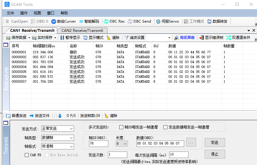
- RT-Thread receives and processes the data.
Figure 4. CAN Test Case 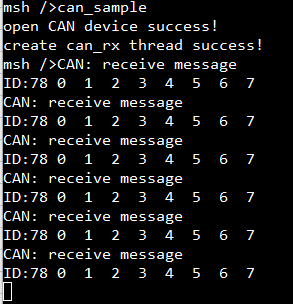
Performance
| Test | Test Condition | Test Result |
|---|---|---|
| Schedule Delay |
|
The average delay is less than 1us, and the maximum delay is 2us. When working with an Ethernet card and in promiscuous mode, the maximum latency is 10us. |
| Interrupt Delay | Test the RX delay of UART at 1.5GHz, from receive > interrupt > finish shell process receives characters. | The whole process takes about 6us. |