Configure and Debug I2C
Hardware Setup
Connect Sense HAT (B) to the 40-pin header illustrated in the following diagram.
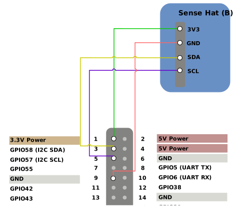
| Sense HAT (B) | 40-Pin GPIO Header | |
|---|---|---|
| Pin Number | Pin Name | |
| 3V3 | 1 | 3.3V Power |
| GND | 9 | GND |
| SDA | 3 | GPIO58 (I2C SDA) |
| SCL | 5 | GPIO57 (I2C SCL) |
Configure DTS File
Configure the jh7110-visionfive-v2.dtsi file that is under /linux/arch/riscv/boot/dts/starfive.
The i2c0 to i2c6 channels are for the I2C bus. You can configure the unoccupied GPIOs as desired. The following is the default setting.
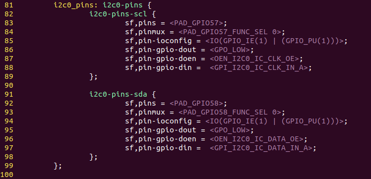
Debug I2C GPIO
To debug I2C:
-
Execute the following command to scan the bus:
i2cdetect -lFigure 3. Example Output 
-
Execute the following command to detect the device:
where, 0 is the I2C bus number.i2cdetect -y -r 0Figure 4. Example Output 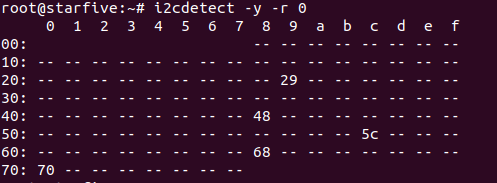
-
Execute the following command to read the register content:
where,i2cget -f -y 0 0x5c 0x0f-
0 is the I2C bus number.
-
0x5C is the I2C device address.
-
0x0f is the memory address.
-
-
Execute the following command to write register data:
where,i2cset -y 0 0x5c 0x11 0x10-
0 is the I2C bus number.
-
0x5C is the I2C device address.
-
0x11 is the memory address.
-
0x10 is the content to be written to the register.
-
-
Execute the following command to read all register values:
where,i2cdump -y 0 0x5c-
0 is the I2C bus number.
-
0x5C is the I2C device address.
-