Configure and Debug UART
Configure dts File
Configure the jh7110-visionfive-v2.dtsi file that is under /linux/arch/riscv/boot/dts/starfive.
Up to 6 channels are supported form UART.
-
Add aliases of uart1 or uart2 on the aliases node. The following is an example:
Figure 1. Alias Example 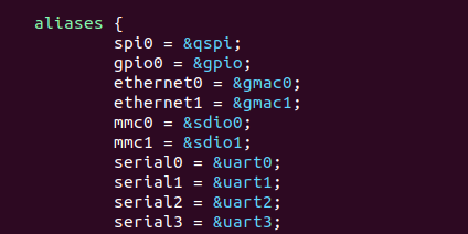
-
Add uart1 or uart2 node on the dts. The following is an example:
Figure 2. Node Example 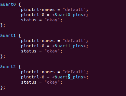
-
Add uart1_pins or uart2_pins node on the
&gpionode.Figure 3. &gpio Example 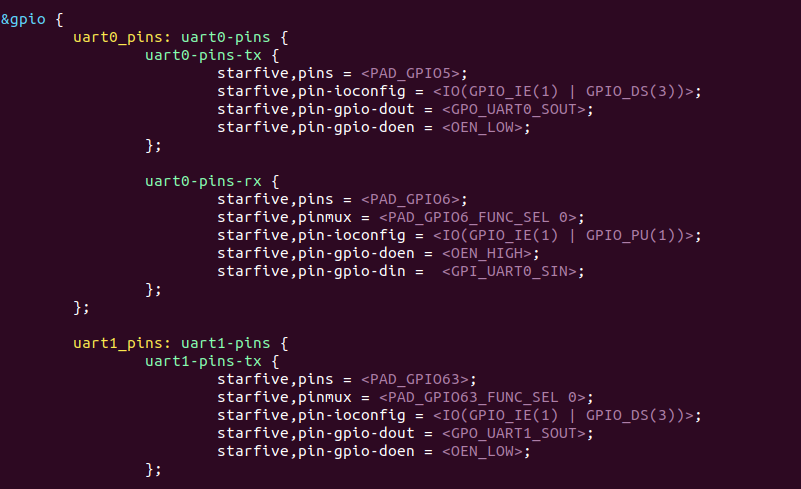
Debug UART Send and Receive Function
-
Set up the hardware.
-
Connect the jumper wires from the USB-to-Serial Converter to the 40-Pin GPIO header of the VisionFive 2 as follows.
Figure 4. Connect the Converter to the Header 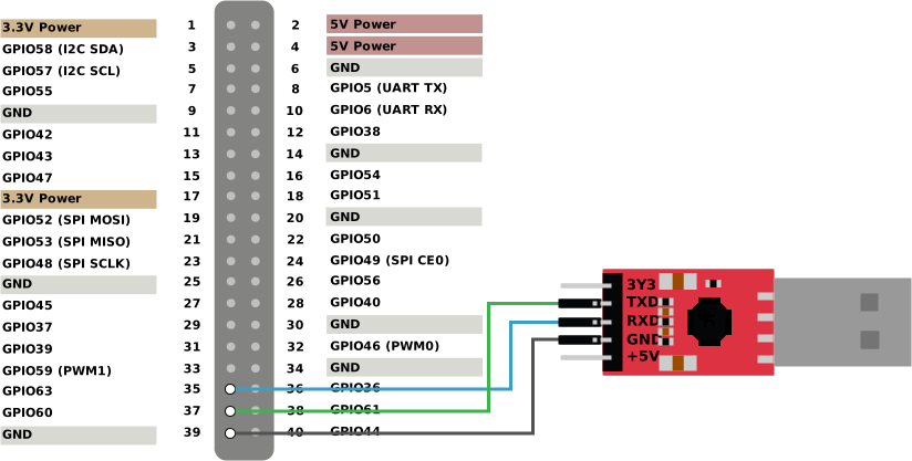
-
Connect the other end of the USB-to-Serial Converter to your device (Windows/Mac/Linux).
-
-
Configure VisionFive 2 minicom.
sudo minicom -s -
Select Serial port setup, and configure minicom as follows.
Figure 5. Example Configuration 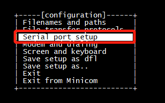
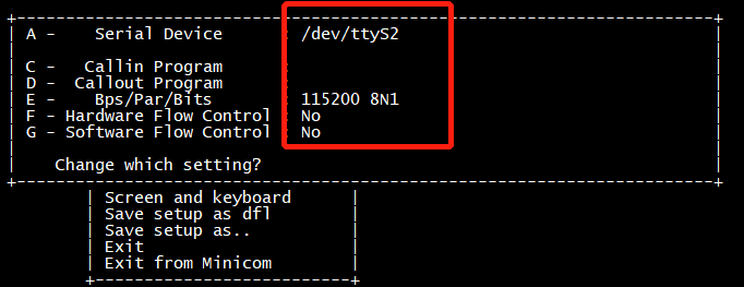
-
Start VisionFive 2 minicom.
minicom -o -D /dev/ttyS1 -
Configure Ubuntu minicom.
sudo minicom -s -
Select Serial port setup, and configure minicom as follows.
Figure 6. Example Configuration 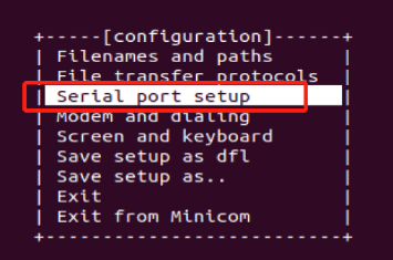
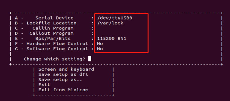 Note: Serial Device can be detected by the
dmesg | grep
                tty
command on Ubuntu. -
Start Ubuntu minicom.
-
To test the UART send function, you can enter characters, such as
hello
                ubuntu
, on the VisionFive 2 minicom. Then you can see the character are outputted on the Ubuntu minicom as follows.Figure 7. Test UART Send 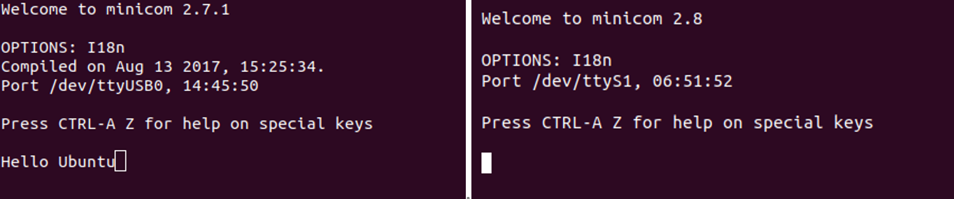
The figure on the left is the Ubuntu minicom interface, and the other is the VisionFive 2 minicom interface.
-
To test the UART receive function, you can enter characters, such as
hello
                visionfive
on the Ubuntu minicom. Then you can see the characters are outputted on the VisionFive 2 minicom.Figure 8. Test UART Receive 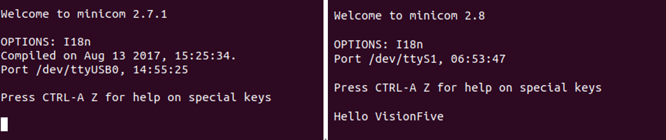
The figure on the left is the Ubuntu minicom interface, and the other is the VisionFive 2 minicom interface.