SCADA Integration
This topic covers the integration of OpenPLC with SCADA (Supervisory Control and Data Acquisition) systems for comprehensive monitoring and control of industrial processes.
SCADA Overview
- Sensors: Measure physical parameters (temperature, pressure, flow)
- RTUs (Remote Terminal Units): Collect sensor data and control actuators
- PLCs: Execute control logic based on sensor inputs
- SCADA Unit: Central data aggregation and monitoring
OpenPLC includes a built-in web-based HMI (accessed via the Monitor menu), which displays data for the local OpenPLC instance and its connected slave devices. For comprehensive monitoring across multiple PLCs and devices, integration with a SCADA system is required.
FUXA Integration
FUXA is a modern, web-based SCADA/HMI software that is well-suited for integration with OpenPLC on VisionFive 2/VisionFive 2 Lite due to its lightweight design and flexible deployment options.
-
Prerequisite: Install nodejs and npm.
- To install
nodejs:
sudo apt-get install nodejs -y -
To install npm:
sudo apt-get install npm -yNote: Network issue may occur in mainland China. Therefore, users in mainland China are recommended to install cnpm by executingnpm install cnpm -g --registry=https://registry.npmmirror.com
- To install
nodejs:
-
Execute the following commands to install FUXA:
git clone https://github.com/frangoteam/FUXA.git
cd FUXA/server/
npm install or cnpm install
Run FUXA: npm start or cnpm start
FUXA Operations
| Operation | Details |
|---|---|
| Access the FUXA Web Interface | Log in to the web server through port 1881 of the device, for example, 192.168.125.38:1881. |
| Add Modbus Component |
|
| Connect to Modbus Devices |
|
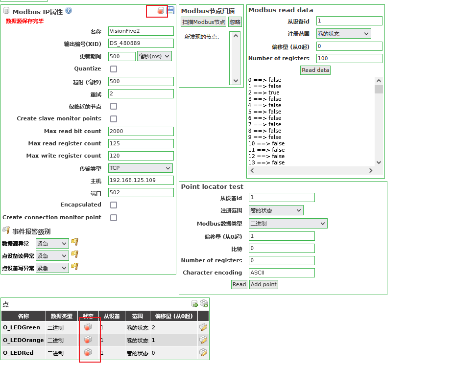
| Add tag for each OpenPLC I/O point | Add a tag for each OpenPLC I/O point to establish
connection:
|
ScadaBR Integration
ScadaBR is a mature, Java-based SCADA platform with extensive industrial protocol support. However, it has more demanding installation requirements.
-
Prerequisite: Install OpenJDK and TomCat9.
-
Download the ScadaBR .war file and put it into the TomCat webapps/ directory. Double-click on the TomCat bin/starup.bat, and then visit
localhost:8080/ScadaBRto enter the ScadaBR interface. -
Enter the default user name and password (admin and admin) when prompted.
ScadaBR Operations
- Click the following icon for Data source in the upper
left corner of the main interface:
Figure 1. Data source 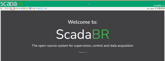
- Select Modbus IP as the data source type and click Add.
- In the Modbus IP Properties screen, set the name, select the appropriate
update time, fill in the host IP, and save the data source. Then select the
value type to be read in the registration range of Modbus read data and
click Read Data to read the current value of the
corresponding type quantity of the corresponding host through Modbus.
Figure 2. Modebus IP Settings 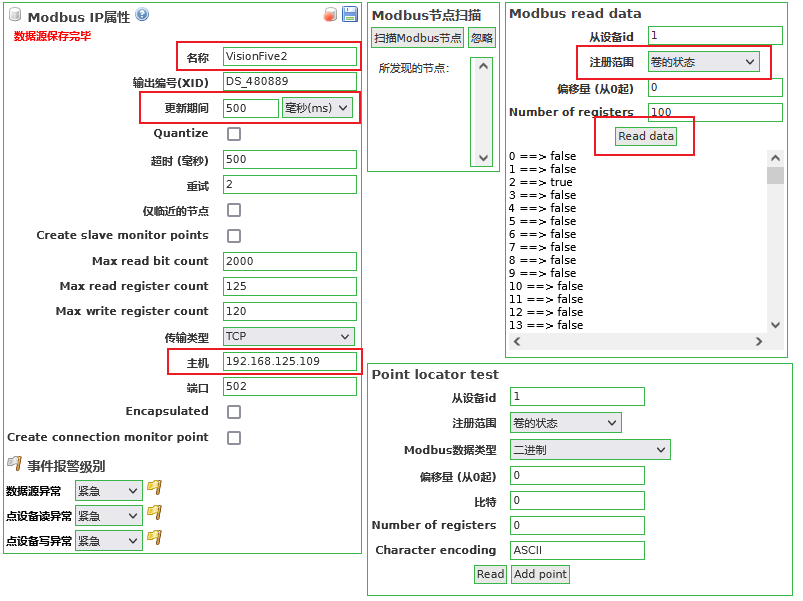
- Click Add point in the Point locator test screen,
enter the Name of the data Point (preferably the same
as ) and Offset (starting at 0, corresponding to 0.0 in
PLC), and save.
Figure 3. Point Settings 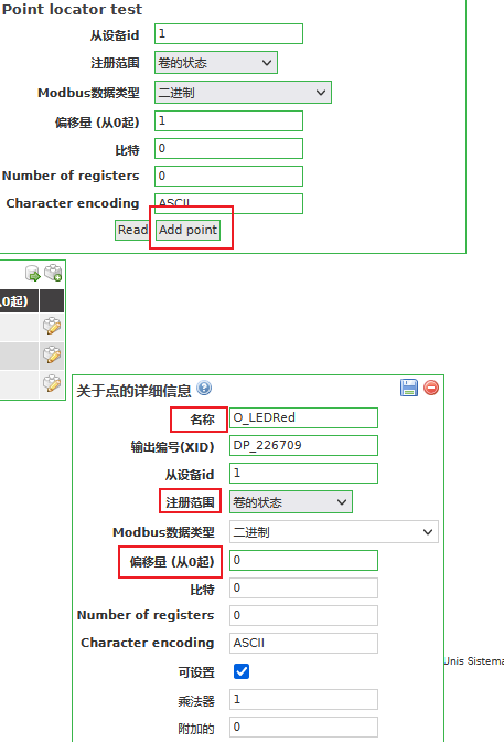
- Click the first icon in the upper left corner to view the value of each data
point of the device in real-time.
Figure 4. Data Point Values