This topic provides an example of integrating OpenPLC with external sensors and actuators
through Modbus-RTU to create a closed-loop temperature control system, which
demonstrates OpenPLC capabilities on VisionFive 2 and VisionFive 2 Lite.
Hardware Preparation
Table 1. Required Hardware Items
Item
Quantity
Description
VisionFive 2
1
Modbus-RTU master device
Arduino UNO
1
Modbus-RTU slave device
LM35 Temperature Sensor
1
Analog temperature sensor
L298N Motor Driver
1
Motor speed control
Voltage Converter
1
5V supply for motor
DC Motor
1
Fan for cooling
Breadboard
1
Prototyping
LED
2
Status indicators (different colors)
Button
2
Manual control inputs
Dupont Wires
Several
Connections
USB2Serial
1
Serial communication
System Architecture
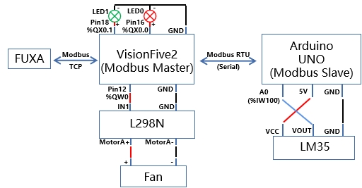
The following diagram illustrates the overall system architecture.Figure 1. Architecture
Since VisionFive 2 lacks native analog input capability, Arduino UNO serves as a
Modbus-RTU slave device that:
Reads the LM35 temperature sensor output
Sends the reading back to VisionFive 2 or VisionFive 2 Lite via Modbus
RTU
Based on the obtained temperature, VisionFive 2 or VisionFive 2 Lite then:
Reflects the temperature is in the normal/high range through the LED
Outputs PWM signals with different duty ratios according to different
temperature ranges
Controls fan start-stop and speed through the DC motor drive module
L298N
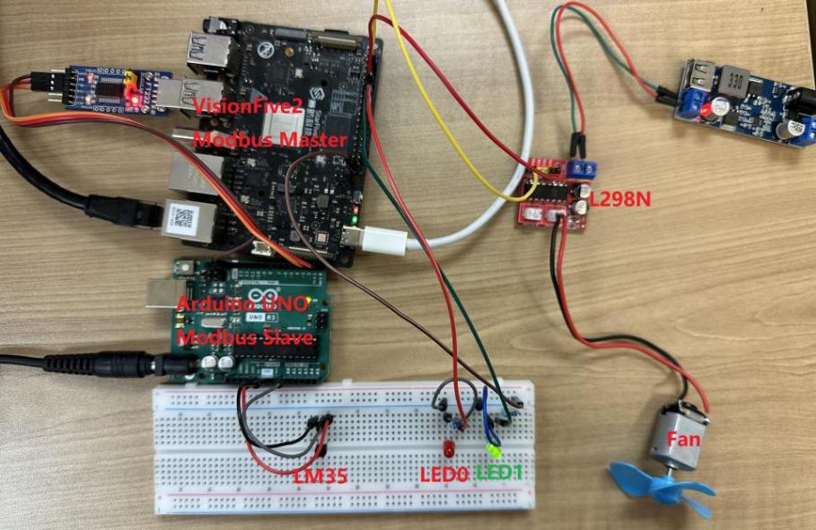
Below is the physical connection:
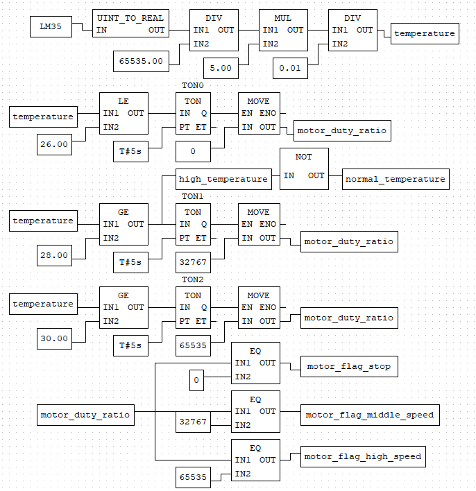
PLC Functional Diagram Program
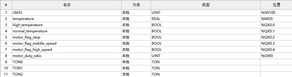
The following diagrams show the PLC functional block program and the variable
definition.
Note: The functional block diagram program is
located in your computer after you download and unzipped the
openplc.zip: openplc\9. Example
temperature_fan.zip.
Figure 2. PLC Functional Block Program
Figure 3. Variable Definition
Temperature Control
OpenPLC analog input resolution is 16 bits, that is, the analog input in OpenPLC
ranges from 0 to 65535. For the LM35 sensor, every 1°C increase results in a 10 mV
output voltage change.
Temperature = LM35 / 65535.00 * 5.00 / 0.01
The following table describes the temperature control logic of the functional diagram
program: