Develop OpenPLC Programs
This topic describes how to install the OpenPLC Editor and create, simulate, and debug IEC 61131-3 compliant PLC programs.
Install OpenPLC Editor
The OpenPLC Editor is an IEC 61131-3 compliant development environment for creating PLC programs.
Download Link: https://openplcproject.com/download/
Reference Documentation: https://openplcproject.com/docs/3-2-creating-your-first-project-on-openplc-editor/
Create a Single Program
- Click NEW in the upper left corner to create a new
project.
Figure 1. Create New Program 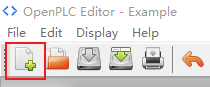
- Create a new POU (Programming Organisation Unit), fill in the program name,
and select the language to use (ladder diagram is selected here):
Figure 2. Create a new POU 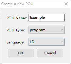
- Select the required elements to form a ladder diagram program:
Figure 3. Select Required Elements 
Here's a basic I/O program:
Figure 4. Basic I/O Program 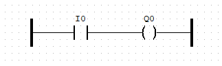
In this program, Q0 will output a high level accordingly when I0 is triggered by a high level. In addition to the basic logical connection, the address of each component needs to be assigned. In this program, I0 and Q0 correspond to the actual digital input and output respectively, and should be assigned usable I/O point addresses, such as:
Figure 5. Example 
- Click Add variable to add a variable that is used in
this program. Generally only need to fill in the corresponding variable
name, variable type and assign the appropriate address.
After programming and assigning the location of variables, click Generate program for OpenPLC Runtime and save the program as a .st file:
Figure 6. Save the Program 
Create Multiple Programs
You can create multiple programs to perform different functions at different scan intervals within a single project.
- Create a program named Part_trig that receives an
input signal and triggers another program.
Figure 7. Part_trig Program 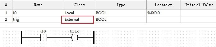 Note:
trig is a variable that triggers another program and needs to be defined as External in this program and declared as Global in Res0:
Figure 8. trig Settings 
- Create another program that is triggered by program ‘Part_trig’. Programs in
different languages can be in the same project, so a new POU using FBD
(Function block diagram) can be created in this project:
Figure 9. Create a New POU 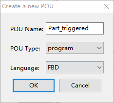
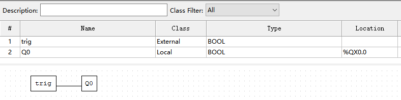
- To run this program, declare an instance for it in the Res.0:
Figure 10. Declare an Instance 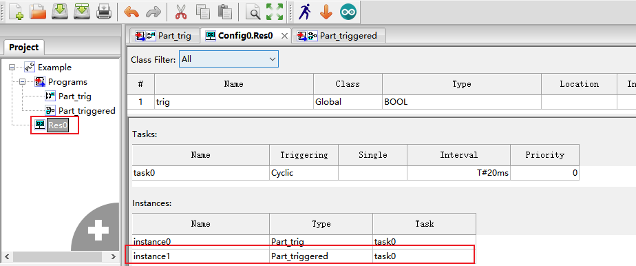
- If programs need to run at different intervals, create new tasks and bind
them to corresponding instances.In the example below:
-
- Task for
part_trig: 20ms interval - Task for
part_triggered: 10ms interval
- Task for
Figure 11. Create and Bound a New Task to an Instance 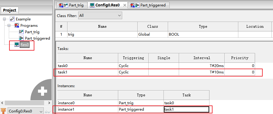
-
Simulate and Debug
The OpenPLC Editor includes a simulation mode for testing programs before deployment.
-
Click Start PLC Simulation and Debug instance in the editor toolbar.
Figure 12. PLC Simulation 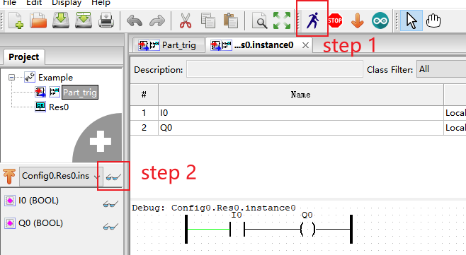
A new tab named Config0.Res0.instance0 appears, displaying the simulation interface.
- Monitor and control values:
- The input point value of I0 can be changed by clicking on the input element in the simulation view.
- Observe the variation of output point Q0 in response to input changes.
- Current values of all points are visible in the Debugger panel on the right side of the interface.
- Use this information to verify that the program logic operates as expected before uploading to the runtime.