Function Block Testing
This topic documents the testing procedures and results for basic PLC function blocks available in OpenPLC, including digital I/O, bistable elements, timers, counters, and arithmetic operations.
Test Setup
The following table lists the hardware preparation and setup required for testing OpenPLC function blocks on VisionFive 2 or VisionFive 2 Lite.
| Item | Quantity | Purpose |
|---|---|---|
| VisionFive 2 / VisionFive 2 Lite | 1 | OpenPLC runtime platform |
| Breadboard | 1 | Circuit prototyping |
| LED | Several | Output indicators |
| Button/Switch | Several | Input signal sources |
| Resistor (100Ω) | Several | LED current limiting |
| L298N Motor Driver | 1 | DC motor speed control |
| DC Motor | 1 | Analog output load |
| Dupont Wires | Several | Circuit connections |
| USB2Serial Converter | 1 | Serial communication |
Digital I/O and Analog Output Test
Verify that OpenPLC correctly reads digital inputs and writes digital and analog outputs.
Test procedures:
- Positive logic test:
- Connect input I1 to a button (active high)
- Connect output O1 to an LED
- Configure O1 to mirror I1 state
- Negative logic test:
- Connect input I2 to a button (active high)
- Connect output O2 to an LED
- Configure O2 to invert I2 state
- Series logic test:
- Inputs I3 and I4 in series
- Output O3 reflects combined result
- Parallel logic test:
- Inputs I5 and another input in parallel
- Output O5 activates when either input is high
- Analog output test:
- Connect L298N PWM input to %QW0
- Drive DC motor with variable speed control
Bistable (SR/RS) Test
Verify the operation of set dominant (SR) and reset dominant (RS) bistable function blocks.
- Inputs I1 and I2 are connected to an RS bistable
- Inputs I3 and I4 are connected to an SR bistable.
- The output of the RS and SR bistable block goes to a rising edge detection and a falling edge detection block respectively.
- The rising edge detector is connected to the set input of the bistable RS0 and the falling edge detector is connected to the reset input of the bistable RS1.
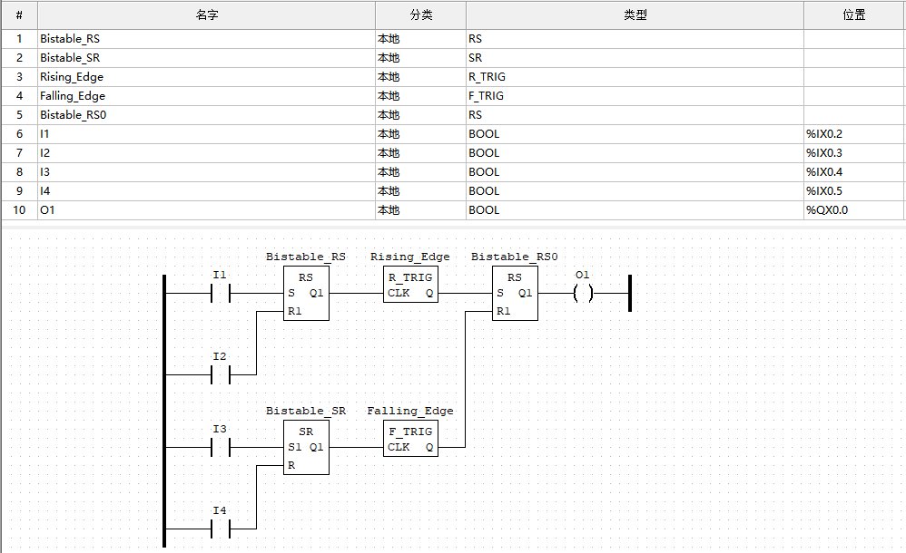
In this test program, the output O1 is set if input I1 is active before inputs I2 and I3. The output should remain set until I2 is triggered or I3-I4 is triggered in sequence.
Timer (TON/TOF) Test
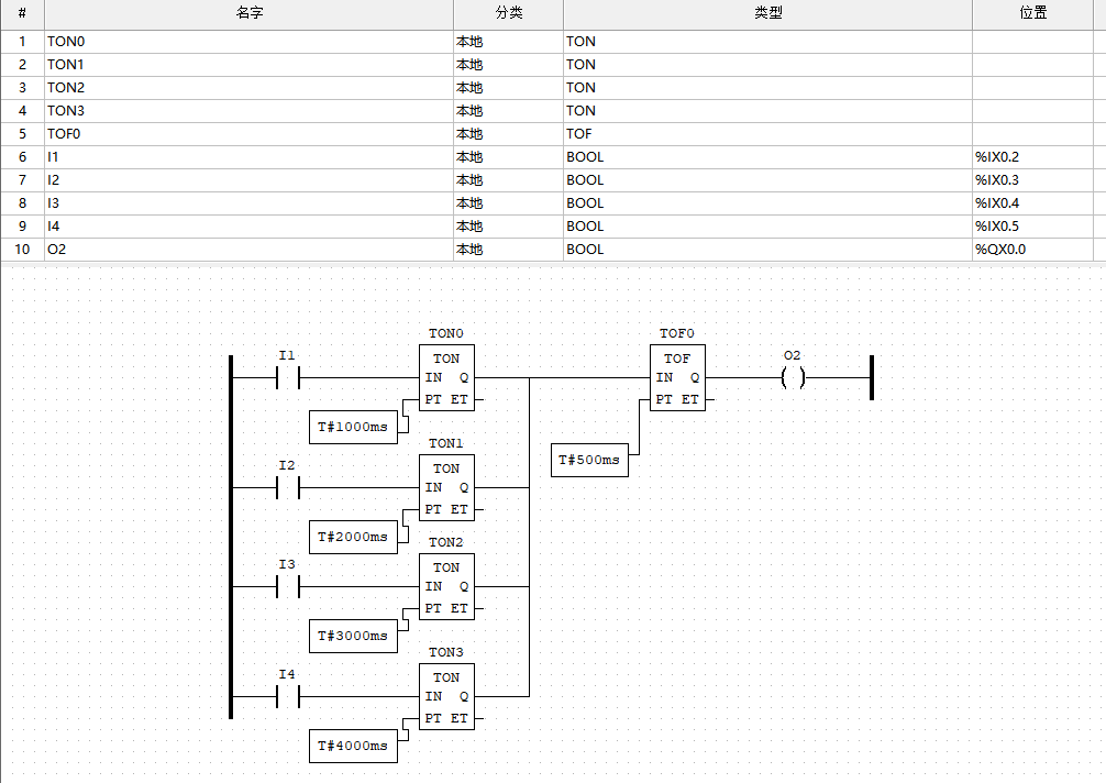
- TON: Output Q activates after input IN is true for PT duration
- TOF: Output Q deactivates after input IN goes false for PT duration
Counter (CTU/CTD) Test
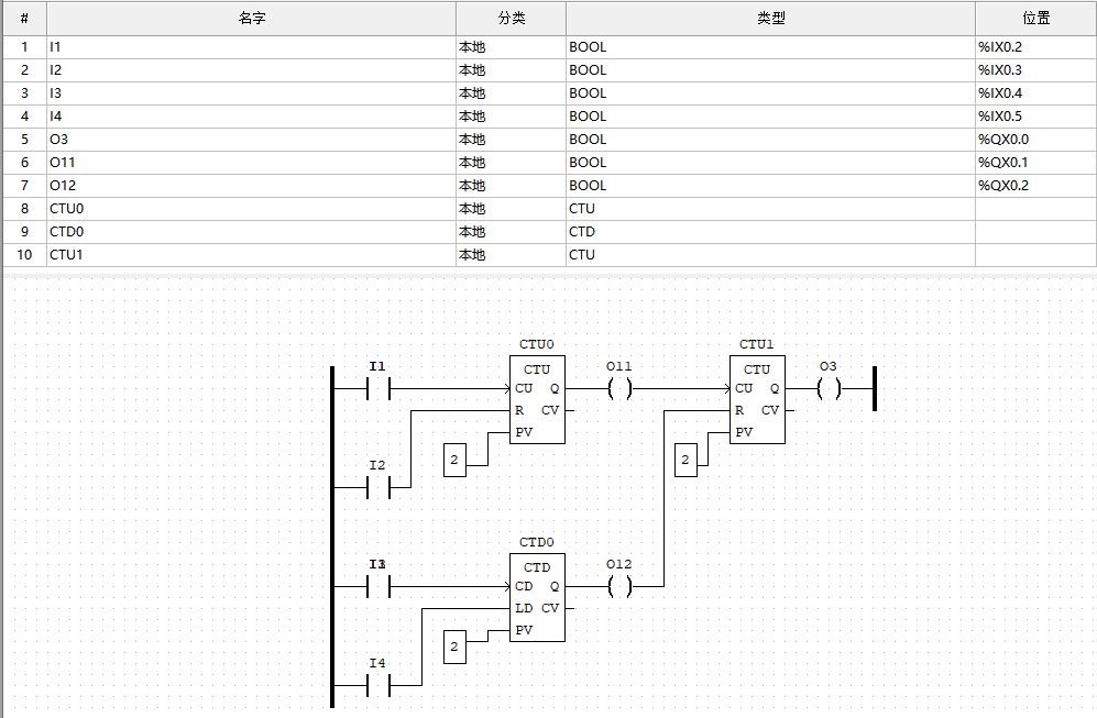
- CTU: A CTU counter increments the internal count variable CV on every rising edge of the input CU. If the value in CV matches the user-defined PV variable, the output Q is set to true. In the event of a rising edge in the input R, the internal count variable CV is reset to zero.
- CTD: CTD counter loads the internal CV variable value from PV on the first rising edge of the input CD and decrements CV on every subsequent rising edge of the input CD. Once CV reaches zero, the output Q is set to true. Upon a rising edge on the input LD, the original PV value is restored to CV.
Arithmetic and Comparison Test
Verify the operation of arithmetic and comparison function blocks.
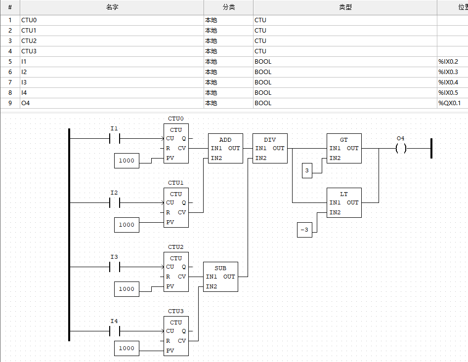
- Connect a CTU counter to each of four inputs (I1, I2, I3, I4).
- Wire the counter variables (CV) to arithmetic blocks.
- Configure the arithmetic operation:
- Connect the result to two comparator blocks:
- Comparator 1: Result > 3
- Comparator 2: Result < -3
- Connect comparator outputs to control output O3.