SPI Driver
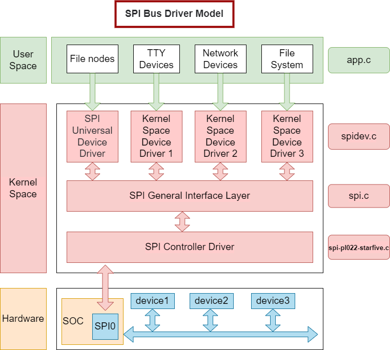
User Space
The user space layer includes all the applications which use the SPI device. In this layer, you can customize the SPI device based on your specific needs.
Kernel Space
- SPI Device Driver Layer:
The Linux kernel does not provide a specific SPI device driver, since the devices on an SPI may vary from case to case. Users have to use the general SPI device driver which can only communicate with the SPI device in synchronous modes. So only some simple and not-so-much-data-consumptive devices are supported in this layer.
In this layer, we provide spidev.c as the standard SPI driver and spi-nand.c as the NAND driver for SPI.
- SPI General Interface Package Layer:
To simplify SPI driver programming and reduce driver program coupling, Linux kernel packages some general programs of drivers for controllers and protocols to form the SPI general interface package layer.
In this layer, we provide the Linux original driver spi.c. - SPI Controller Driver Layer:
This layer is the focus of our attention, it will be introduced in detail in the following parts of the document.
In this layer, we provide the driver spi-pl022-starfive.c.
Hardware
The hardware layer is the physical device layer. In this layer, SPI controllers and the connected SPI devices communicate with CPU via SPI bus.
Device Tree Source Code
     spi0: spi@10060000 {
        compatible = "arm,pl022", "arm,primecell";
        reg = <0x0 0x10060000 0x0 0xl0000>;
        clocks = <&clkgen JH7110_SPI0_CLK_APB>;
        clock-names = "apb_pclk";
        resets = <&rstgen RSTN_U0_SSP_SPI_APB>;
        reset-names = "rst_apb";
        interrupts = <38>;
        /* shortage of dma channel that not be used */
        /* dmas = <&dma 14 1>, <&dma 15 1>;*/
        /* dma-names = "rx","tx";*/
        arm,primecell-periphid = <0x00041022>;
        num-cs = <1>;
        #address-cells = <1>;
        #size-cells = <0>;
        status = "disabled";
The following table describes the configuration parameters:
| Parameter | Description |
|---|---|
| compatible | Compatibility information, used to associate the driver and its target device |
| reg | Register base address "0x10060000" and range "0x10000" |
| clocks | The clocks used by the SPI module |
| clock-names | The names of the clocks used by the SPI module |
| resets | The reset signals used by the SPI module |
| reset-names | The names of the reset signals |
| interrupts | Hardware interrupt ID |
| primecell-periphid | The peripheral ID of the SPI device |
| num-cs | The total count of the chip select signals |
| status |
The work status of the SPI module. To enable the module, set this bit to okay. To disable the module, set this bit to disabled. |
Source Code Structure
- drivers/spi/spi.c: The file contains source code for the SPI driver framework.
- drivers/spi/spidev.c: The file contains the source code to create the SPI device node and use it in user mode.
- drivers/amba/bus.c: The file contains the source code to register platform devices through AMBA bus.
- driver/spi/spi-pl022-starfive.c: The file contains the source code of SPI controller driver on the JH7110 platform.
- tools/spi/spidev_test.c: The file contains the SPI test tool in user mode.