GPIO Driver
The JH7110 SoC platform integrates a pin controller that enables developers to configure the functions and properties of individual pins or pin groups. The Linux kernel pin control (pinctrl) driver can help developers with the following tasks:
- Locate and name all the pins managed by the pin controller.
- Implement pin multiplexing.
- Provide options for pin configuration, including drive strength, power-up, power-down, and data attributes.
- Interact with the GPIO subsystem.
- Implement pin interrupt.
Block Diagram
The following figure displays the block diagram of the JH7100 GPIO pin control (pinctrl) driver module.
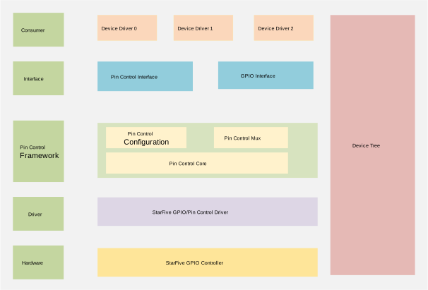
| Layer | Description |
|---|---|
| Consumer | The pin control interfaces and GPIO interfaces used by the device driver, such as SDIO and PCIe. |
| Interface | The pin control and GPIO interfaces for users. See Interface Description for more information. |
| Pintrl Framework | The original Linux system pin control framework. The framework enables developers to configure functions and properties of individual pins or pin groups |
| Driver | The GPIO and pin control drivers of the JH7110 SoC platform. |
| Hardware | The GPIO controller of the JH7110 SoC platform. |
Pin Control Framework
- Pinctrl Core: The core layer of the pin control framework. The states–default, sleep, and idle–corresponds to the power management states of pin control.
- Pinctrl Mux: Manages pin multiplexing functions.
- Pinctrl Conf: Manages pin configuration settings.
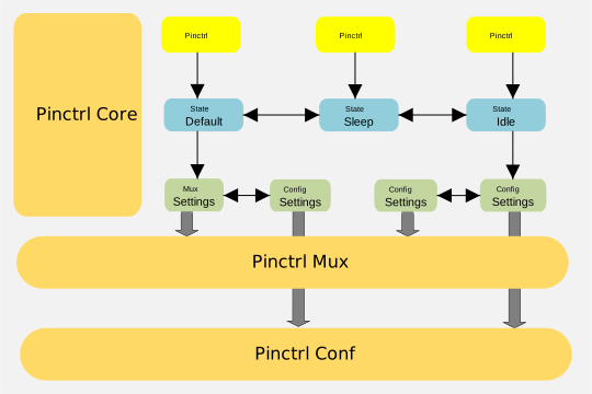
Pin configurations may differ depending on the system operating mode. For example, the default pin configuration applies to normal mode, whereas the power-saving pin configuration applies to standby mode. Therefore, you can use the pin control framework to manage pin configurations according to the operating mode of the device.
Device Tree Source Code
        gpio: gpio@13040000 {
                compatible = "starfive,jh7110-sys-pinctrl";
                reg = <0x0 0x13040000 0x0 0x10000>;
                reg-names = "control";
                clocks = <&clkgen JH7110_SYS_IOMUX_PCLK>;
                resets = <&rstgen RSTN_U0_SYS_IOMUX_PRESETN>;
                interrupts = <86>;
                interrupt-controller;
                #gpio-cells = <2>;
                ngpios = <64>;
                status = "okay";
        };

        gpioa: gpio@17020000 {
                compatible = "starfive,jh7110-aon-pinctrl";
                reg = <0x0 0x17020000 0x0 0x10000>;
                reg-names = "control";
                resets = <&rstgen RSTN_U0_AON_IOMUX_PRESETN>;
                interrupts = <85>;
                interrupt-controller;
                #gpio-cells = <2>;
                ngpios = <4>;
                status = "okay";
        };
The following table describes the source code parameters:
| Parameter | Description |
|---|---|
| compatible | Compatibility information, used to associate the driver and its target device. |
| reg | Register base address "0x13040000" and range "0x10000". |
| reg-names | Names of the registers used by the GPIO module. |
| clocks | The clocks used by the GPIO module. |
| clock-names | The names of the clocks used by the GPIO module. |
| resets | The reset signals used by the GPIO module. |
| interrupts | Hardware interrupt ID. |
| status |
The work status of the GPIO module. To enable the module, set this bit to okay. To disable the module, set this bit to disabled. |
|
Note: Make sure you do not change the bits
of gpio-cells and ngpios.
|
|
Source Code Structure
linux
├── drivers
│   ├── pinctrl
│   │   ├── core.c
│   │   ├── core.h
│   │   ├── devicetree.c
│   │   ├── devicetree.h
│   │   ├── pinconf.c
│   │   ├── pinconf-generic.c
│   │   ├── pinconf.h
│   │   ├── pinmux.c
│   │   ├── pinmux.h
│   │   ├── starfive
│   │   │   ├── Kconfig
│   │   │   ├── Makefile
│   │   │   ├── pinctrl-starfive.c
│   │   │   ├── pinctrl-starfive.h
│   │   │   └── pinctrl-starfive-jh7110.c

├── include
│   ├── dt-bindings
│   │   ├── pinctrl
│   │   │   ├── starfive,jh7110-pinfunc.h
│   ├── linux
│   │   ├── pinctrl
│   │   │   ├── consumer.h
│   │   │   ├── devinfo.h
│   │   │   ├── machine.h
│   │   │   ├── pinconf-generic.h
│   │   │   ├── pinconf.h
│   │   │   ├── pinctrl.h
│   │   │   ├── pinctrl-state.h
│   │   │   └── pinmux.h