MIPI Driver
The display subsystem, named as dom_vout_top in the JH-7110 system, includes front-end video data capture, display controller and display interface, such as RGB IF, HDMI and MIPI.
JH-7110 integrates MIPI DSI v1.3.1 TX Controller IP (DSITX) and MIPI DPHY M31 for the LCD module.
Block Diagrams
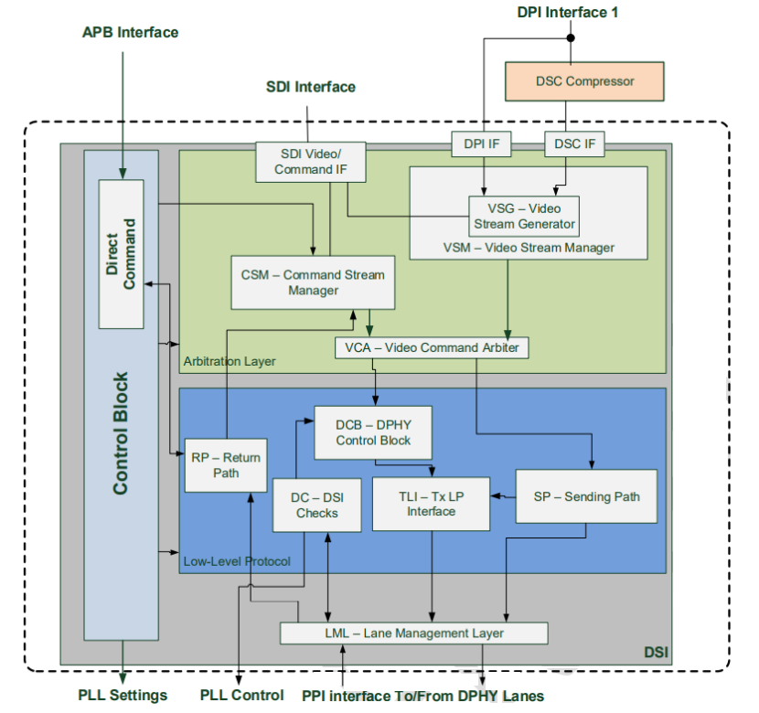
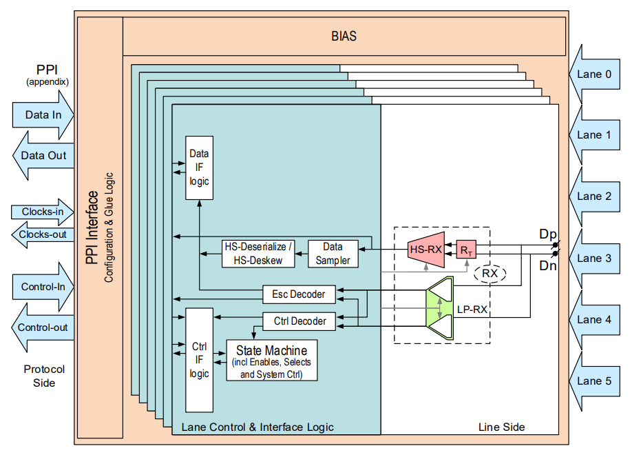
MIPI Driver Source Code
linux-5.15.0
└-- drivers
└-- | --gpu
| -- | -- | -- drm
| -- | -- | -- |-- verisilicon
| -- | -- | -- | -- | -- inno_mipi.c
| -- | -- | -- | -- | -- inno_mipi.h
MIPI DSI Device Tree Code
The device tree source code of the MIPI DSI is stored in the jh7110.dtsi file.
linux/arch/riscv/boot/dts/starfive/jh7110.dtsi:
		 mipi_dsi: mipi@295d0000 {
			compatible = "starfive,jh7110-mipi_dsi","cdns,dsi";
			reg = <0x0 0x295d0000 0x0 0x10000>;
			interrupts = <98>;
			reg-names = "dsi";
			clocks = <&clkvout JH7110_U0_CDNS_DSITX_CLK_SYS>,
				 <&clkvout JH7110_U0_CDNS_DSITX_CLK_APB>,
				 <&clkvout JH7110_U0_CDNS_DSITX_CLK_TXESC>,
				 <&clkvout JH7110_U0_CDNS_DSITX_CLK_DPI>;
			clock-names = "sys", "apb", "txesc", "dpi";
			resets = <&rstgen RSTN_U0_CDNS_DSITX_DPI>,
				 <&rstgen RSTN_U0_CDNS_DSITX_APB>,
				 <&rstgen RSTN_U0_CDNS_DSITX_RXESC>,
				 <&rstgen RSTN_U0_CDNS_DSITX_SYS>,
				 <&rstgen RSTN_U0_CDNS_DSITX_TXBYTEHS>,
				 <&rstgen RSTN_U0_CDNS_DSITX_TXESC>;
			reset-names = "dsi_dpi", "dsi_apb", "dsi_rxesc",
					"dsi_sys", "dsi_txbytehs", "dsi_txesc";
			phys = <&mipi_dphy>;
                       phy-names = "dphy";
			status = "disabled";

			port {
				dsi_out_port: endpoint@0 {
					remote-endpoint = <&panel_dsi_port>;
				};
				dsi_in_port: endpoint@1 {
					remote-endpoint = <&mipi_out>;
				};
			};
| Parameter | Description |
|---|---|
| compatible | Compatibility information, used to associate the driver and its target device |
| reg | Register base address "0x295d0000" and range
"0x10000". |
| interrupts | Hardware interrupt ID |
| reg-names | Name of the register |
| clocks | The clocks used by the MIPI DSI controller |
| clock-names | The names of the clocks used by the MIPI DSI controller |
| resets | The reset signals used by the MIPI DSI controller |
| reset_names | The names of the reset signals |
| phys | References the MIPI DPHY node (defined in the same dtsi) |
| phy-names | MIPI DPHY name |
| status |
The work status of the MIPI DSI controller. To enable the module, set this bit to okay. To disable the module, set this bit to disabled. |
| port | Data input and output of the DSI controller following the OF graph standard |
MIPI DPHY Device Tree Code
The device tree source code of the MIPI DPHY is stored in the jh7110.dtsi file.
linux/arch/riscv/boot/dts/starfive/jh7110.dts:
		mipi_dphy: mipi-dphy@295e0000{
			compatible = "starfive,jh7110-mipi-dphy-tx","m31,mipi-dphy-tx";
			reg = <0x0 0x295e0000 0x0 0x10000>;
			clocks = <&clkvout JH7110_U0_MIPITX_DPHY_CLK_TXESC>;
			clock-names = "dphy_txesc";
			resets = <&rstgen RSTN_U0_MIPITX_DPHY_SYS>,
				 <&rstgen RSTN_U0_MIPITX_DPHY_TXBYTEHS>;
			reset-names = "dphy_sys", "dphy_txbytehs";
			#phy-cells = <0>;
			status = "disabled";
		};
| Parameter | Description |
|---|---|
| compatible | Compatibility information, used to associate the driver and its target device |
| reg | Register base address "0x295E0000" and range
"0x10000". |
| clocks | The clocks used by the MIPI DPHY |
| clock-names | The names of the clocks used by the MIPI DPHY |
| resets | The reset signals used by the MIPI DPHY |
| reset_names | The names of the reset signals |
| status |
The work status of the MIPI DPHY. To enable the module, set this bit to okay. To disable the module, set this bit to disabled. |