VisionFive 2 supports two MIPI display output channel, one is 1C2L (2-lane MIPI DSI), and
the other is 1C4L (4-lane MIPI DSI). StarFive provides the tool package dsi_tool for you to calculate DSI timing. This topic
describes how to use the tool for timing calculation and set the timing into the Linux
driver to light the screen.
About DSI Tool Package
The DSI tool package includes the following components:
StarFive_DSI_Tool_v2.0.exe
input.md: Stores input for MIPI DSI timing calculate.
This file provides example parameters for your reference.
output.txt: This file is the timing result generated by
running ./run.sh based on
input.md.
./run.sh: Script used to generate
output.txt
Prepare Timing Calculate Input
Configure the input.md file to update the timing calculate
parameters according to your screen specifications.
The following table describes the parameters in the input.md
file:
Table 1. Timing Calculate Input Parameters
Parameter
Description
bpp
Bit per pixel
pixelclock*
The pixel clock
hactive*
Horizontal effective pixels
hfront_porch*
Horizontal front porch, delay before horizontal
synchronization signal
hback_porch*
Horizontal back porch, delay after horizontal synchronization
signal
hsync_len*
Horizontal pulse width, the length of the horizontal
synchronization signal
vactive*
Vertical effective pixels
vfront_porch*
Vertical front porch, delay before vertical synchronization
signal
vback_porch*
Vertical back porch, delay after vertical synchronization
signal
vsync_len*
Vertical pulse width, the length of the vertical
synchronization signal
dlanes
MIPI DSI lane number
dsi_hblank_ratio
The ratio of hsa, hbp, and hfp of DSI
timing. It is used to allocate the horizontal blanking of the
final calculated DSI timing, which can be
0. If any of the three values are
0, the default ratio is used.
r_hsa
The ratio of hsa of DSI timing, which can be
0. If the value is
0, the DSI hsa, hbp,
hfp will use the default ratio.
r_hbp
The ratio of hbp of DSI timing, which can be
0. If the value is
0, the DSI hsa, hbp,
hfp will use the default ratio.
r_hfp
The ratio of hfp of DSI timing, which can be
0. If the value is
0, the DSI hsa, hbp,
hfp will use the default ratio.
pixclk_source
Pixel clock source, corresponding to PLL2 of JH-7110 (default
is 1188M). To make changes to PLL2, you will have to modify this
parameter.
Note:* means you shall obtain the
parameter values from the screen manufacturer.
Generate DSI Timing Result
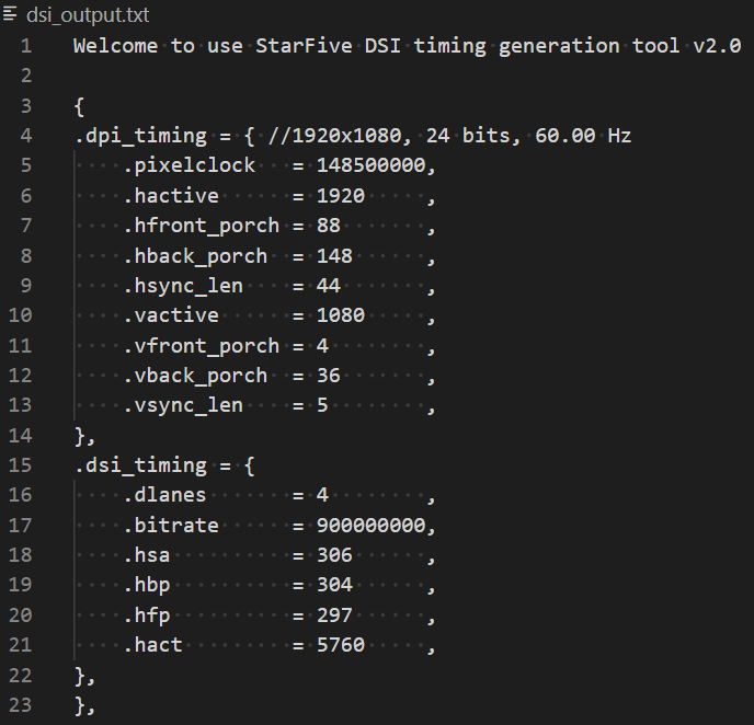
Run the following command to generate the output.txt file which
contains the DSI timing calculate result. The result is calculated based on your
input.md.
./run.sh
The following is an example output:Figure 1. Example Output
Apply Timing to IC2L MIPI Channel
Apply the timing calculation result to the IC2L MIPI channel.
To support a new screen for the 1C2L MIPI channel, modify the driver file
starfive_drm_seeedpanel.c under
/Linux/drivers/gpu/drm/verisilicon.
This driver file servers as an i2c device by default,
and the probe interface uses the i2c
command to read the panel ID, and verify whether the current screen is
connected properly based on the return value. When debugging a new
screen:
If the i2c command can read the panel ID, the
probe function needs to support the
i2c interface; In seed_ panel_
enable function, the panel should be enabled
according to the specific command of i2c.
If the i2c command cannot read panel ID, you
are recommended to remove the i2c related
command, then the probe process can be
completed, so that the screen is in connected status by
default.
Note: It is necessary to
remove all i2c read/write
command.
Add dpi_timing, which is the timing of the panel, in the
panel driver. It corresponds to starfive_drm_seedpanel.c
under the \linux\drivers\gpu\drm\verisilicon, which
maps to seeed_panel_modes.
Enter starfive_drm_seedpanel.c file.
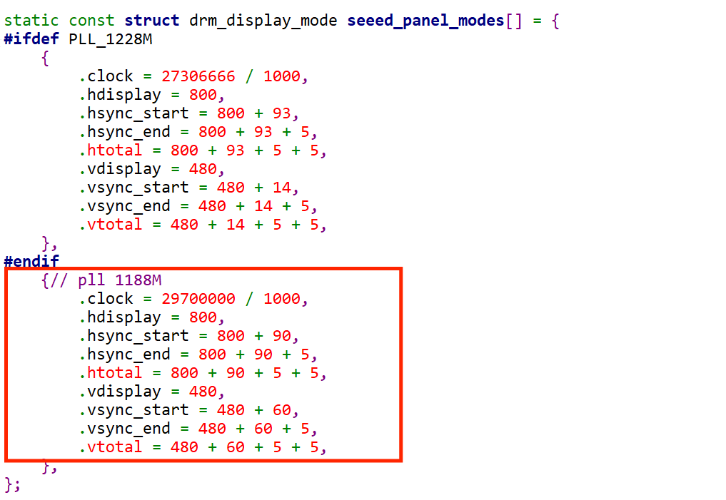
Modify the parameters of PLL 1188M under this function according to
the output.txt file.Figure 2. Modify the Parameters
Tip:
clock = pixelclock/1000
hdisplay = hactive
hsync_start = hactive + hfp
hsync_end = hactive + hfp + hbp
htotal = hactive + hfp + hbp+ hsync_len
vdisplay = vactive
vsync_start = vactive + vfp
vsync_end = vactive + vfp + vbp
vtotal = vactive + vfp + vbp + vsync_len
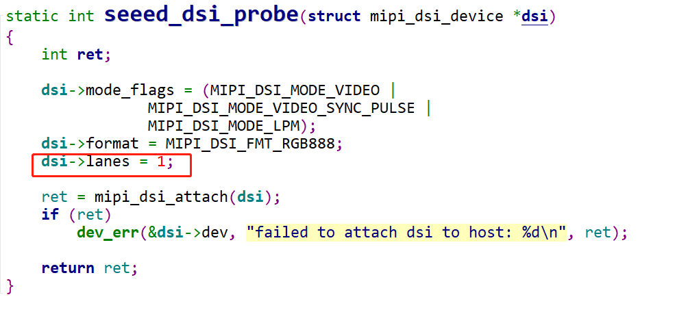
After configuration, it is synchronized to the DC controller driver
and MIPI DSI driver. For example, to set the lanes to
1, you can change the corresponding
parameters in the input file. Figure 3. Example InputThe corresponding driver code is shown in the following
figure:Figure 4. Driver Code
Follow the steps below to configure MIPI DSI.
Open the starfive_drm_dsi.c file under the
path of \linux\drivers\gpu\drm\verisilicon
in Linux.
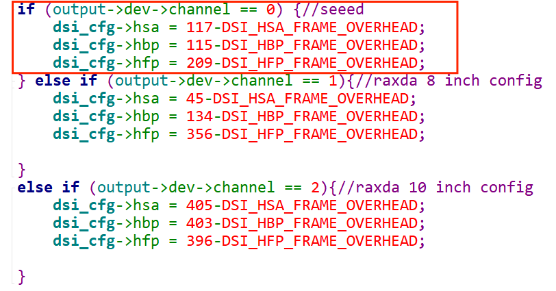
Locate the cdns_dsi_mode2cfg function and
set hsa, hbp and
hfp in channel 0 to 36,
108, 288 respectively.
Note: Modifying parameters should based on
the corresponding channel. 1C2L corresponds to channel 0
while 1C4L corresponds to channel 1.
Figure 5. hsa hbp hfp
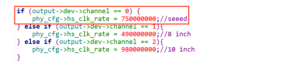
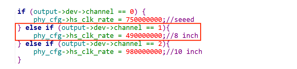
Locate the cdns_dsi_adjust_phy_config
function and set the bitrate to
750000000.Figure 6. Bitrate
Tip: The
hs_clk_rate in the figure
means bitrate.
Apply Timing to IC4L MIPI Channel
Apply the timing calculation result to the IC4L MIPI channel.
To support a new screen for the 1C4L MIPI channel, modify the driver file
panel-jadard-jd9365da-h3.c under
/Linux/drivers/gpu/drm/panel.
This driver file servers as an i2c device by default,
and the probe interface uses the i2c
command to read the panel ID, and verify whether the current screen is
connected properly based on the return value. When debugging a new
screen:
If the i2c command can read the panel ID, the
probe function needs to support the
i2c interface; In seed_ panel_
enable function, the panel should be enabled
according to the specific command of i2c.
If the i2c command cannot read panel ID, you
are recommended to remove the i2c related
command, then the probe process can be
completed, so that the screen is in connected status by
default.
Note: It is necessary to
remove all i2c read/write
command.
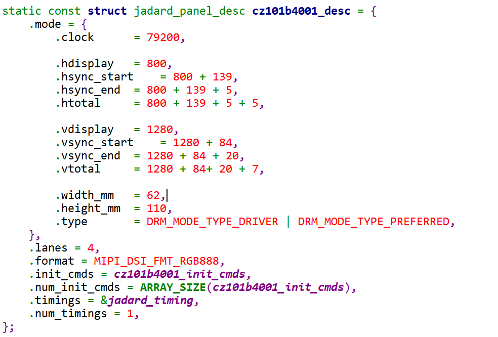
Add dpi_timing, which is the timing of the panel, in the
panel driver. It corresponds to cz101b4001_desc under the
\linux\drivers\gpu\drm\panel.
Enter starfive_drm_seedpanel.c file.
Modify the parameters of PLL 1188M under this function according to
the output.txt file.Figure 7. Modify the Parameters
Tip:
clock = pixelclock/1000
hdisplay = hactive
hsync_start = hactive + hfp
hsync_end = hactive + hfp + hbp
htotal = hactive + hfp + hbp+ hsync_len
vdisplay = vactive
vsync_start = vactive + vfp
vsync_end = vactive + vfp + vbp
vtotal = vactive + vfp + vbp + vsync_len
After configuration, it is synchronized to the DC controller driver
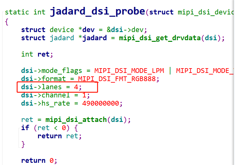
and MIPI DSI driver. For example, to set the lanes to
4, you can change the corresponding
parameters in the input file. The corresponding driver code is shown
in the following figure:Figure 8. Driver Code
Follow the steps below to configure MIPI DSI.
Open the starfive_drm_dsi.c file under the
path of \linux\drivers\gpu\drm\verisilicon
in Linux.
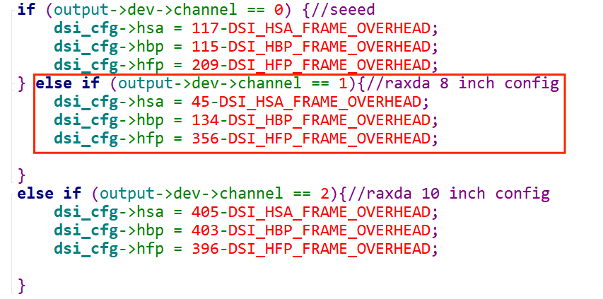
Locate the cdns_dsi_mode2cfg function and
set hsa, hbp and
hfp in channel 1 to 66,
64, and 57 respectively.
Note: Modifying parameters should based on
the corresponding channel. 1C2L corresponds to channel 0
while 1C4L corresponds to channel 1.
Figure 9. hsa hbp hfp
Locate the cdns_dsi_adjust_phy_config
function and set the bitrate to
750000000.Figure 10. Bitrate
 Tip:

 Tip: The hs_clk_rate in the figure means bitrate.
 Tip:
 Tip: The hs_clk_rate in the figure means bitrate.