MIPI Driver Configuration
Enable MIPI in Kernel menuconfig
-
Under the root directory of freelight-u-sdk, run the following command to enter the kernel menu configuration GUI.
make linux-menuconfig -
Enter the Device Drivers menu.
-
Enter the Graphics support menu.
-
In the Graphics support menu, select the DRM Support option.
-
In the Graphics support menu, select the Starfive MIPI DSI Select option.
-
To enable the M31 DPHY, go back to Device Drivers menu, enter the PHY Subsystem menu, and select the Starfive M31 MIPI DPHY TX Driver option.
-
Save your change and exit the kernel configuration dialog.
Enable modetest in menuconfig
Enable the Install Test Programs in the kernel configuration so that you can use the modetest tool in the kernel for testing.
-
Under the root directory of freelight-u-sdk, type the following command to enter the kernel menu configuration GUI.
make buildroot_initramfs-menuconfig -
Enter the Target packages > Libraries > libdrm menu.
-
Select the Install test programs option, or you may select ALL options under this menu.
Figure 1. Install Test Programs 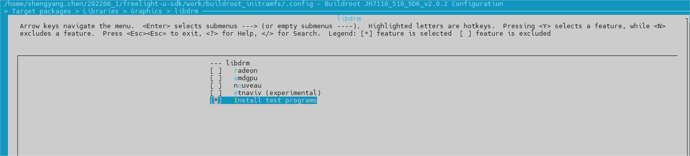
Result: After you have completed all the above configuration, you can use the modetest tool in kernel for testing.
-
Save your change and exit the kernel configuration dialog.
Enable/Disable MIPI at Board Level
In the jh7110-common.dtsi file, you can enable or disable MIPI at the board level which overrides the corresponding settings at the SoC level which is defined in the jh7110.dtsi file.
linux/arch/riscv/boot/dts/starfive/jh7110-common.dtsi:
&mipi_dsi {
	status = "okay";
};linux/arch/riscv/boot/dts/starfive/jh7110-common.dts:
&mipi_dphy {
status = "okay";
};Configure MIPI DSI Port at Board Level
To activate and fully utilize the DSI controller’s output port for display, a matching MIPI DSI panel device node must be defined and connected through the Device Tree OF graph binding.
This procedure demonstrates how to attach a MIPI DSI panel as an I2C slave and establish the cross-file graph connection between the panel and the DSI controller output port.
jh7110-common.dts, and then declare
the Seeed DSI panel as its I2C slave child node. The panel’s endpoint references the
pre-defined dsi_out_port from jh7110.dtsi, forming
one half of the bidirectional display pipeline link (DSI TX output to panel
input).// jh7110-common.dts (board-level DTS)
&i2c2 {
clock-frequency = <100000>;
i2c-sda-hold-time-ns = <300>;
i2c-sda-falling-time-ns = <510>;
i2c-scl-falling-time-ns = <510>;
auto_calc_scl_lhcnt;
pinctrl-names = "default";
pinctrl-0 = <&i2c2_pins>;
status = "okay";
// Board-defined MIPI DSI panel I2C slave node
seeed_plane_i2c@45 {
compatible = "seeed_panel";
reg = <0x45>; // I2C slave address of panel controller IC
// Panel input endpoint to connect DSI output port
port {
panel_dsi_port: endpoint {
remote-endpoint = <&dsi_out_port>;
};
};- Board file (
jh7110-common.dts): Panel endpoint points to DSI output&dsi_out_port - SoC header (
jh7110.dtsi): The MIPI DSI controller’s output endpoint pre-declares the reverse referenceremote-endpoint = <&panel_dsi_port>.
Seeed Panel Driver API Reference
Enable, disable, or obtain seeed panel information using the following API.
| Function | Description | Prototype |
|---|---|---|
| seeed_panel_enable | Initializes the DSI link and lane configuration, enables the LCD power supply, and turns on the backlight. |
|
| seeed_panel_disable | Disables the LCD power supply and turns off the backlight. |
|
| seeed_panel_get_modes | Gets registration information of panel. |
|