Connect Slave Device via Modbus TCP
Modbus TCP enables communication over Ethernet. In the typical setup, two VisionFive 2 boards are used: one as the Modbus master and one as the Modbus slave.
Hardware Preparation
| Item | Quantity | Note |
|---|---|---|
| VisionFive 2 or VisionFive 2 Lite | 2 | One configured as Master, the other as Slave |
| Ethernet cable or network switch | 1 | For direct connection or LAN connectivity |
| Breadboard | 1 | For Slave board wiring |
| LED | 2 | Preferably two different colors |
| Button | 2 | For digital input testing |
| Dupont wires | Several | For breadboard connections |
Hardware Circuit
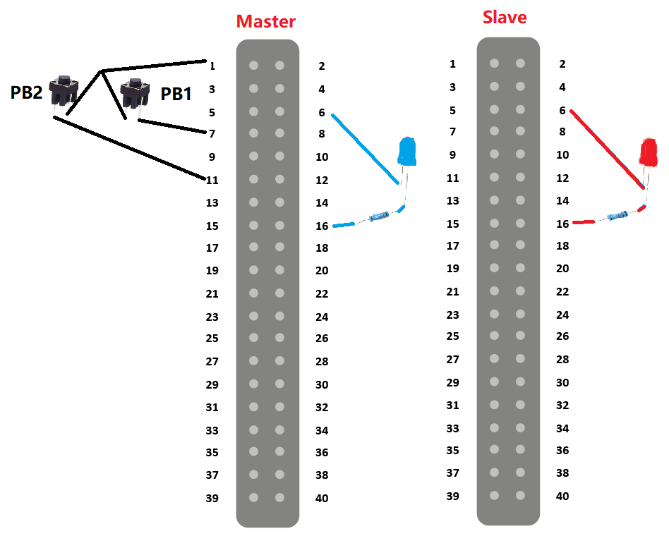
The button that controls the blue/red LED flashing is connected to %IX0.0 and %IX0.1 of the master device, the blue LED is connected to %QX0.0 of the master device, and the red led is connected to %QX0.0 of the slave device, which is %QX100.0 of the master device. There is no electrical connection between the master and slave devices.
For details about the pin mapping for the 40-pin GPIO header on the master/slave board, see I/O Capabilities and Pin Mapping References.
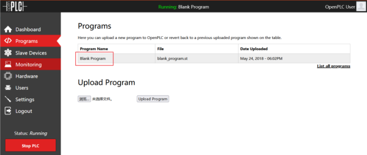
Run Blank Program on Slave Board
Add Slave Device on Master Board
-
Open the OpenPLC web interface:
http://<Master-IP>:8080 -
Navigate to Slave Devices in the left menu.
-
Click Add New Device.
Figure 3. Slave Device Settings 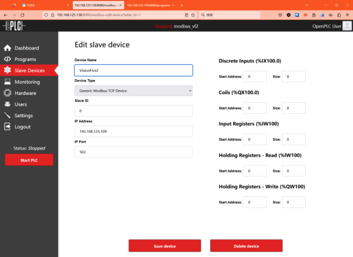
-
Fill in the slave device properties.
Table 1. Slave Device Properties Property Description Device Name Descriptive name for the slave VisionFive 2 board Device Type Protocol selection. Select Generic Modbus-TCP Device. Slave ID ID pf the slave board IP Address IP address of the slave board IP Port Modbus TCP port (default: 502) -
Map the I/O points and registers between the master device and slave device. For example, if there are 8 digital input points, 8 digital output points, and 1 analog output point configured in the master device, setting the size of the following properties accordingly.
Table 2. I/O Point and Register Mappings Property Size Value Discrete Inputs 8 Coils 8 Holding Registers - Write 1
Upload Test Program to Master Device
For details about uploading a program, see Upload a Program.
Verification
-
Check the Runtime Logs on the Master board's dashboard. A successful Modbus-TCP device connection is indicated by a log message confirming the slave device is connected.
Figure 4. Successful Connection 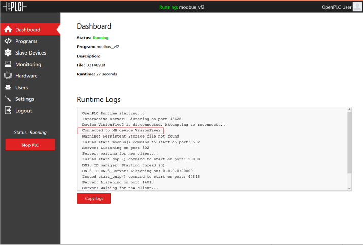
-
Press the button that controls the red LED blinking on the master board. Check whether the red LED on the slave board starts blinking to confirm that the master and slave devices are communicating properly.