Kernel Driver Configuration for Ethernet
This section describes the Linux kernel network driver implementation for the JH-110 Ethernet interface.
Source Code Structure
The JH-7110 Ethernet driver resides in the Linux kernel source tree
at:
linux/drivers/net/ethernet/stmicro/stmmacIt includes the following major configuration files:
| File | Description |
|---|---|
| stmmac.h | GMAC driver header file that defines macros, data structures, and internal function interfaces |
| dwmac-starfive-plat.c | GMAC driver specific configuration specific to the StarFive DWMAC platform |
| stmmac_main.c | GMAC driver public interface on the DWMAC platform |
Enable GMAC in Kernel Menu
Follow the steps below to enable GMAC support in the kernel menu dialog.
- Under the root directory of freelight-u-sdk, type the
following command to enter the kernel menu configuration GUI.
make linux-menuconfig - Enter the Networking support > Networking options menu, and select supported network protocols.
- Enter the Device Drivers menu.
- Enter the menu and select the GMAC drivers you expect the system to
support.
Figure 1. Ethernet Driver Support 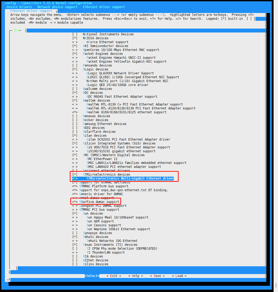
- Save your change before you exit the kernel configuration dialog.
Device Tree Configuration - SoC Level
The SoC-level device tree include file (jh7110.dtsi) defines the
GMAC hardware
blocks.
gmac0: ethernet@16030000 {
			compatible = "starfive,dwmac","snps,dwmac-5.10a";
			reg = <0x0 0x16030000 0x0 0x10000>;
			clock-names = "gtx",
				"tx",
				"ptp_ref",
				"stmmaceth",
				"pclk",
				"gtxc",
				"rmii_rtx";
			clocks = <&clkgen JH7110_GMAC0_GTXCLK>,
				 <&clkgen JH7110_U0_GMAC5_CLK_TX>,
				 <&clkgen JH7110_GMAC0_PTP>,
				 <&clkgen JH7110_U0_GMAC5_CLK_AHB>,
				 <&clkgen JH7110_U0_GMAC5_CLK_AXI>,
				 <&clkgen JH7110_GMAC0_GTXC>,
				 <&clkgen JH7110_GMAC0_RMII_RTX>;
			resets = <&rstgen RSTN_U0_DW_GMAC5_AXI64_AHB>,
				 <&rstgen RSTN_U0_DW_GMAC5_AXI64_AXI>;
			reset-names = "ahb", "stmmaceth";
			interrupts = <7>, <6>, <5> ;
			interrupt-names = "macirq", "eth_wake_irq", "eth_lpi";
			max-frame-size = <9000>;
			phy-mode = "rgmii-id";
			snps,multicast-filter-bins = <64>;
			snps,perfect-filter-entries = <128>;
			rx-fifo-depth = <2048>;
			tx-fifo-depth = <2048>;
			snps,fixed-burst;
			snps,no-pbl-x8;
			snps,force_thresh_dma_mode;
			snps,axi-config = <&stmmac_axi_setup>;
			snps,tso;
			snps,en-tx-lpi-clockgating;
			snps,en-lpi;
			snps,write-requests = <4>;
			snps,read-requests = <4>;
			snps,burst-map = <0x7>;
			snps,txpbl = <16>;
			snps,rxpbl = <16>;
			status = "disabled";
};| Parameter | Description |
|---|---|
| compatible | Compatibility information, used to associate the driver and its target device |
| reg | Register base address and offset |
| clocks | The clocks used by the Ethernet module. Usually this parameter is filled with the system clock source or the clock of the module. |
| clock-names | Names of the clocks |
| resets | The reset signals used by the Ethernet module |
| reset-names | Names of the reset signals |
| interrupts | Hardware interupt ID |
| interrupt-names | Interrupt names |
| phy-mode | The Ethernet PHY mode, for example, rgmii or rmii. |
| snaps, * | See Synopsis documentation for PHY specific parameters. |
| status |
The work status of the Ethernet module. To enable the module, set this bit to okay. To disable the module, set this bit to disabled. |
Device Tree Configuration - Board Level
Board-level GMAC enablement and PHY properties are configured by overriding the
SoC-level defaults in jh7110-common.dtsi.
The following example enables GMAC0 and configures the Motorcomm YT8531 PHY delay parameters for RGMII-ID mode:
&gmac0 {
	status = "okay";
	#address-cells = <1>;
	#size-cells = <0>;
	phy0: ethernet-phy@0 {
		rxc_dly_en = <1>; //This field is used to set whether to enable the 2ns time delay of the receiver in RGMII mode. 1: Enable. 0: Disable.
		rx_delay_sel = <0>; // This field is used to configure the receiver clock time delay, 150 ps per step width, accepted range: 0x0 - 0xf.
		tx_delay_sel_fe = <5>; //This field is used to configure the transmitter clock time delay in 10 M/100 M mode, 150 ps per step width, accepted range: 0x0 - 0xf.
		tx_delay_sel = <0xa>; //This field is used to configure the transmitter clock time delay in 1,000 M mode, 150 ps per step width, accepted range: 0x0 - 0xf.
		tx_inverted_10 = <0x1>; //This field is used to set whether to enable the transmitter clock inversion in 10 M mode. 1: Enable. 0: Disable.
		tx_inverted_100 = <0x1>; //This field is used to set whether to enable the transmitter clock inversion in 100 M mode. 1: Enable. 0: Disable.
		tx_inverted_1000 = <0x1>; //This field is used to set whether to enable the transmitter clock inversion in 1,000 M mode. 1: Enable. 0: Disable.
	};
};